Rotary impact tool

a rotary impact and tool technology, applied in the direction of screwdrivers, power driven tools, wrenches, etc., can solve the problems of insufficient fastening torque of the fastening member to prevent over-fastening, inability to transitively tighten the fastening bode, and inability to perform continuous tightening operation, independent from the normal fastening operation of the conventional rotary impact tool

Inactive Publication Date: 2005-12-01
MATSUSHITA ELECTRIC WORKS LTD
View PDF16 Cites 77 Cited by
  • Summary
  • Abstract
  • Description
  • Claims
  • Application Information

AI Technical Summary

Benefits of technology

[0008] A purpose of the present invention is to provide a rotary impact tool, which can perform the tight fastening operation independently from the normal fastening operation, continuously.

Problems solved by technology

In the actual fastening work, there, however, are many cases that the fastening torque of the fastening member is insufficient for preventing the over fastening.
Thus, if the user judges that the fastening of the fastening member is completed due to stop of the driving of the motor, the tight fastening bode cannot be transitive.
The conventional rotary impact tool with the tight fastening mode, however, cannot be performed the tight fastening operation independently from the normal fastening operation, continuously.

Method used


Image

  • Rotary impact tool
  • Rotary impact tool
  • Rotary impact tool

Examples


Embodiment Construction

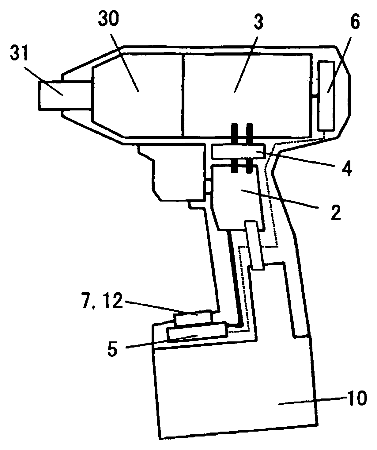
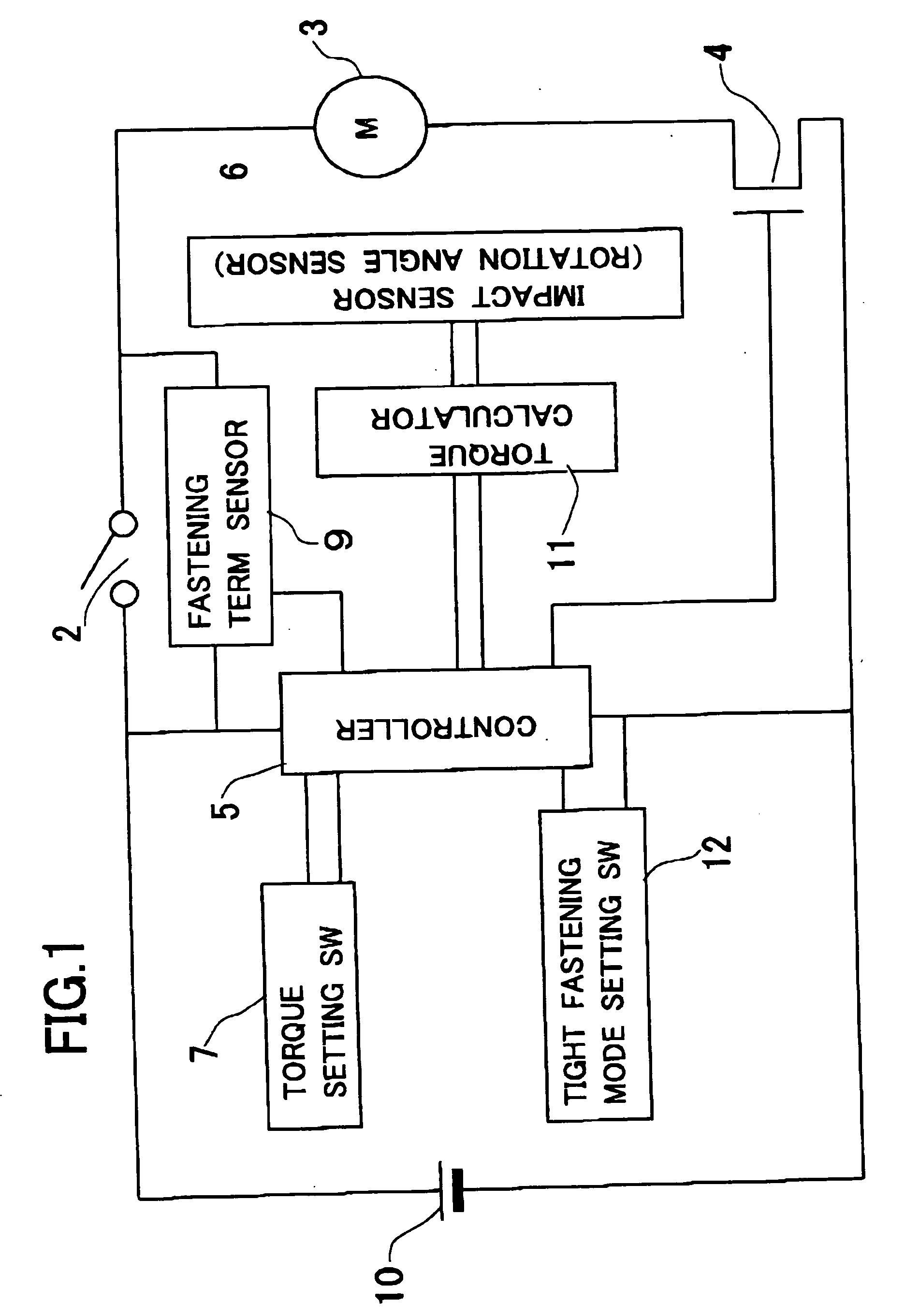
[0020] A rotary impact tool in accordance with a first embodiment of the present invention is described. A block configuration of the rotary impact tool is shown in FIG. 1. The rotary impact tool comprises a main switch 2 used for controlling the fastening operation, a motor 3, a switching device 4 used for on and off of driving the motor 3, a controller (control circuit) 5, an impact sensor 6 which further serves as a rotation angle sensor, a torque setting switch 7 used fir setting a fastening torque, a fastening term sensor (sensing circuit) 9, a battery 10 as a power source, a torque calculator (calculating circuit) 11 and a tight fastening mode setting switch 12. The battery 10, the main switch 2, the motor 3 and the switching device 4 are connected in series, and the series circuit is connected in parallel with the controller 5.

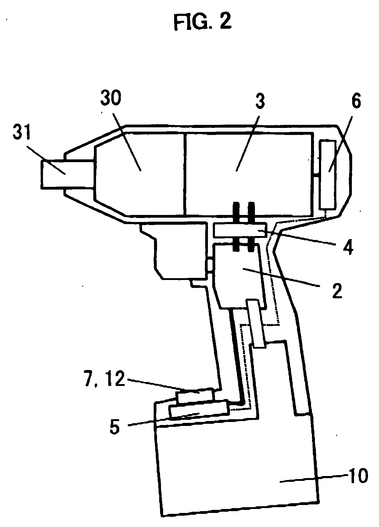
[0021]FIG. 2 shows schematic configuration of the rotary impact tool, and FIG. 3 shown specific example of a driving mechanism 30 for performing faste...


PUM


Abstract

A rotary impact tool can be used continuously for fastening a plurality of fastening members such as screws, bolts or nuts in tight fastening mode. The rotary impact tool comprises a rotary driving mechanism including a motor for rotating a driving shaft, a hammer engaged with the driving shaft, an output shaft to which a driving force is applied by impact blow of the hammer, a main switch operated by a user for controlling fastening operation, and a controller for controlling on and off of the motor. The controller has a normal fastening mode and a tight fastening mode, and a tight fastening mode setting switch used for setting the tight fastening mode is further comprised. When the tight fastening mode setting switch is switched on, the controller continuously drives the rotary driving mechanism so as to perform tight fastening operation continuously.

Description

BACKGROUND OF THE INVENTION [0001] 1. Field of the Invention [0002] The present invention relates to a rotary impact tool such as an impact wrench or an impact driver used for fastening or loosening of fastening member such as a screw, a bolt or a nut. [0003] 2. Description of the Related Art [0004] A rotary impact tool which can stop the driving of the motor automatically when a fastening torque reaches to a predetermined value is conventionally provided. In the actual fastening work, there, however, are many cases that the fastening torque of the fastening member is insufficient for preventing the over fastening. For preventing occurrence of the insufficient fastening torque, Japanese Laid-Open Patent Publication No. 2001-129767 shows a rotary impact tool which can fasten the fastening member a little more further to stop the fastening of the fastening member in normal fastening torque (it is called tight fastening mode). [0005] In such a conventional rotary impact tool, when the ...

Claims


Application Information

Patent Timeline
Patent Type & Authority Applications(United States)
IPC IPC(8): B25B21/02B25B23/14B25B23/147B25D1/00
CPCB25B23/1405B25B21/02
Inventor SHIMIZU, HIDENORIOHASHI, TOSHIHARUKAWAI, KOZOSAINOMOTO, YOSHINORISAWANO, FUMIAKIMIYAZAKI, HIROSHIARIMURA, TADASHIMATSUMOTO, TATSUHIKO
Owner MATSUSHITA ELECTRIC WORKS LTD
Why Eureka
Try Eureka