Permanent magnet motor

a permanent magnet, permanent magnet technology, applied in the direction of magnetic circuit rotating parts, dynamo-electric machines, magnetic circuit shape/form/construction, etc., can solve the problems of exerting an adverse influence on uneven rotation and positioning accuracy, and achieve the effect of reducing the torque of the coil

Inactive Publication Date: 2005-12-01
ORIENTAL MOTOR
View PDF3 Cites 39 Cited by
  • Summary
  • Abstract
  • Description
  • Claims
  • Application Information

AI Technical Summary

Benefits of technology

[0011] a value obtained by dividing the radius of the rotor by the radius of curvature of a permanent magnet surface facing towards the stator is set at a value such as to decrease cogging torque.
[0014] According to the present invention, cogging torque can be decreased.

Problems solved by technology

Fluctuations in running torque caused by a change in magnetic flux distribution in a gap made by the positional relationship between the slot of stator and the permanent magnet at the time when the permanent magnet 10 is rotated, what is called cogging torque (torque in a state in which no current is caused to flow in the coil), occur, which exerts an adverse influence on uneven rotation and positioning accuracy.

Method used


Image

  • Permanent magnet motor
  • Permanent magnet motor
  • Permanent magnet motor

Examples


Embodiment Construction

[0024] An embodiment of the present invention will now be described in detail with reference to the accompanying drawings.

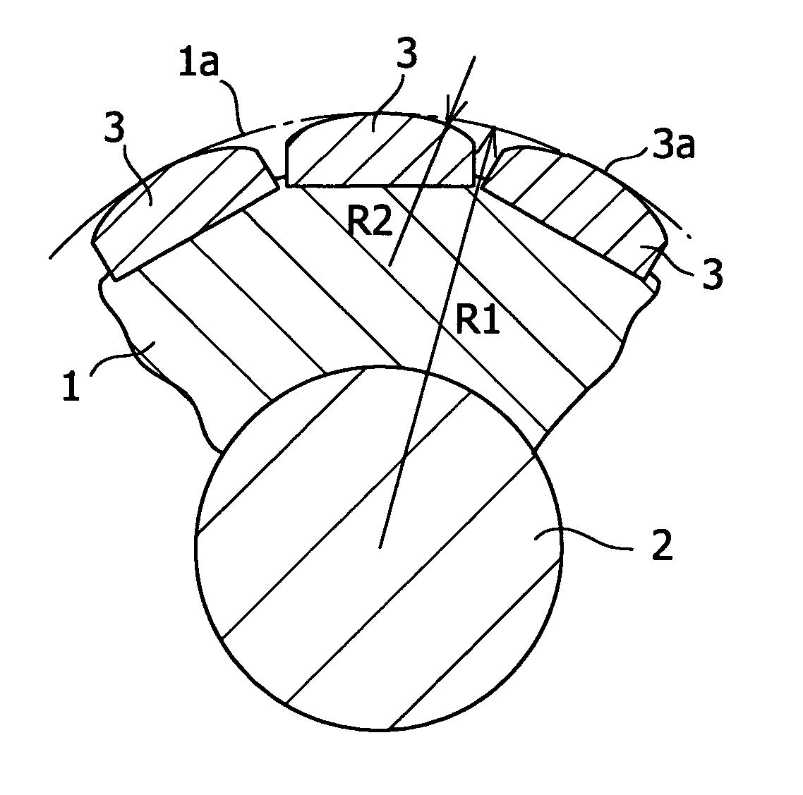
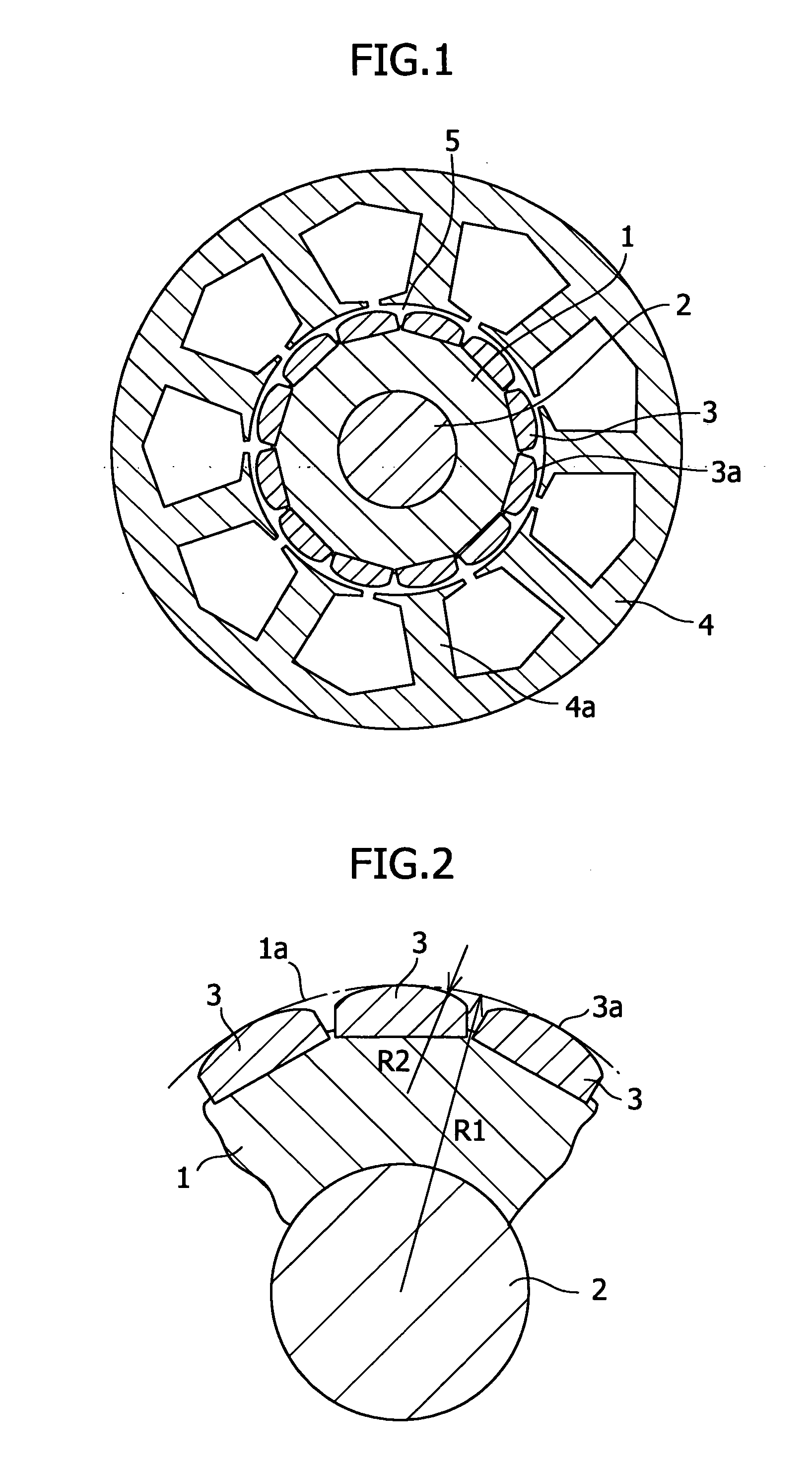
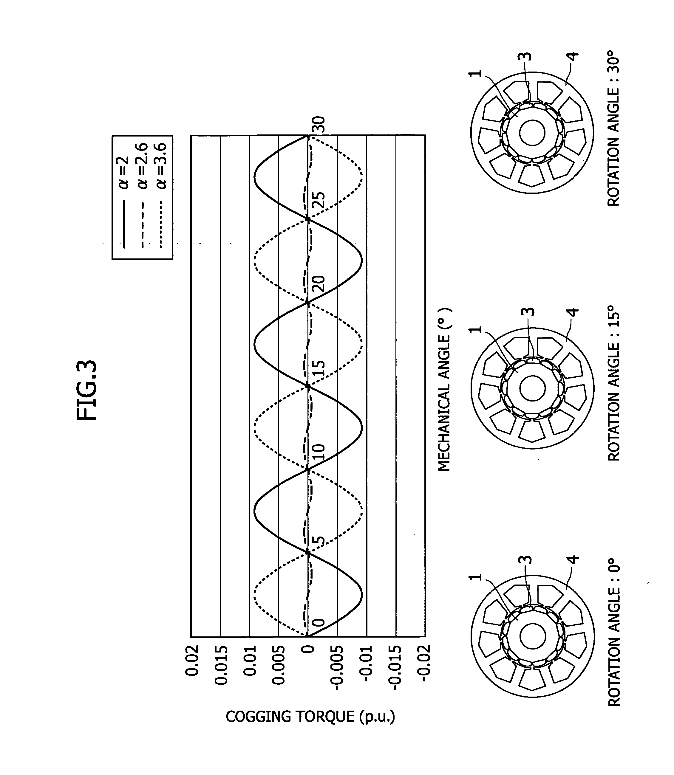
[0025]FIG. 1 is a schematic view showing a permanent magnet motor, FIG. 2 is a schematic view showing the radius of the outer peripheral surface of a rotor and the radius of curvature of a permanent magnet portion facing towards a stator, and FIG. 3 is a characteristic diagram showing the relationship of characteristics of cogging torque to rotation angle of rotor.

[0026] In FIG. 1, reference numeral 1 denotes a rotor supported on a rotating shaft 2. The rotor 1 is provided with twelve permanent magnets 3 arranged at fixed intervals along the circumferential direction at the peripheral edge thereof. The permanent magnets 3 each are formed with an arcuate surface 3a the outer peripheral surface of which has a fixed curvature along the circumferential direction. Reference numeral 4 denotes a stator disposed around the rotor 1 with a gap 5 being provided with resec...


PUM


Abstract

In a permanent magnet motor consisting of a rotor 1, which is supported on a rotating shaft 2 and has twelve permanent magnets 3 arranged at fixed intervals in the circumferential direction in the peripheral edge portion thereof, and a stator 4, which is disposed around the rotor 1 with a gap being provided with respect to the rotor 1 and has nine magnetic poles 4a, each having a coil wound thereon, arranged at fixed intervals in the circumferential direction so as to face towards the outer peripheral surface of the rotor 1, a value obtained by dividing the radius of the rotor 1 by the radius of curvature of a permanent magnet surface facing towards the stator is set at a value such as to decrease cogging torque. Thereby, there is provided a permanent magnet motor in which the radius of an arcuate shape which can minimize cogging torque is theoretically verified, by which the optimum radius can be determined limitedly for a permanent magnet motor consisting of a rotor having twelve permanent magnets and a stator having nine magnetic poles.

Description

BACKGROUND OF THE INVENTION AND RELATED ART STATEMENT [0001] The present invention relates to a permanent magnet motor and, more particularly, to a permanent magnet motor consisting of a rotor having twelve permanent magnets and a stator having nine magnetic poles. [0002] Generally, permanent magnet motors have been used widely as control motors including servomotors because of their high efficiency and controllability. [0003]FIG. 8 shows a conventional permanent magnet motor. This permanent magnet motor includes a rotor 12, which is formed by affixing C-shaped permanent magnets 10 in the radial direction onto the surface of a rotor yoke 11, and a stator consisting of a stator yoke 13 having a plurality of slots 15 arranged via a gap and a coil 17 wound on teeth 14. For this permanent magnet motor, the number of poles of the permanent magnet 10 is six, and the number of teeth is eighteen. [0004] The torque of an AC servomotor etc. requiring highly accurate torque control must have s...

Claims


Application Information

Patent Timeline
Patent Type & Authority Applications(United States)
IPC IPC(8): H02K1/22H02K1/27H02K21/16
CPCH02K1/278H02K1/2781
Inventor DOMEKI, HIDEOYAMANAKA, YOSHIYASU
Owner ORIENTAL MOTOR
Why Eureka
Try Eureka