Radiator structures

a technology of radio antennas and structures, applied in the direction of flexible aerials, collapsible antennas, resonant antennas, etc., can solve the problems of stringent weight and space constraints on active array apertures, stringent weight and space limitations imposed by launch vehicle capabilities,

Active Publication Date: 2005-12-01
RAYTHEON CO
View PDF12 Cites 56 Cited by
  • Summary
  • Abstract
  • Description
  • Claims
  • Application Information

AI Technical Summary

Problems solved by technology

Some active array apertures are under stringent weight and space constraints.
For example, space-based arrays need to be delivered into space, and so there are stringent weight and space limitations imposed by the launch vehicle capabilities.

Method used


Image

  • Radiator structures
  • Radiator structures
  • Radiator structures

Examples


Embodiment Construction

[0026] In the following detailed description and in the several figures of the drawing, like elements are identified with like reference numerals.

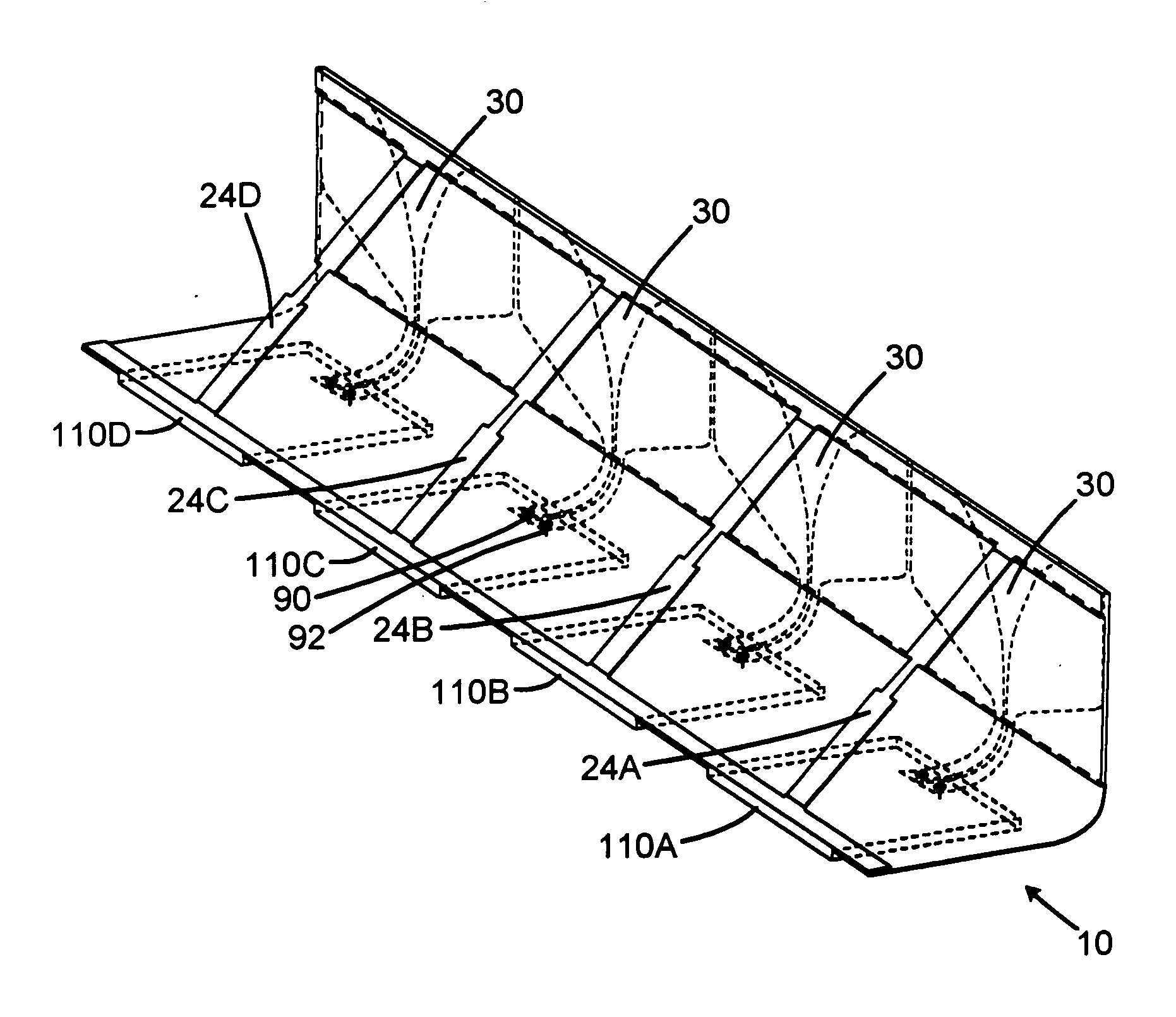
[0027] Embodiments of a thin lightweight wide band radiating element and array structure are described. Exemplary applications for these embodiments include space based active array antennas. The radiator is foldable or rollable into a stored configuration for low volume storage within a rocket, for example, to increase the amount of antenna aperture that can be stored within a fixed volume, e.g. in the rocket prior to launch. When the antenna is unfolded or unrolled during deployment, the radiator may be configured to pop-up by itself to the proper operating shape and configuration, or to be deployed by a dielectric line. In other embodiments, the antenna can be fixed in position.

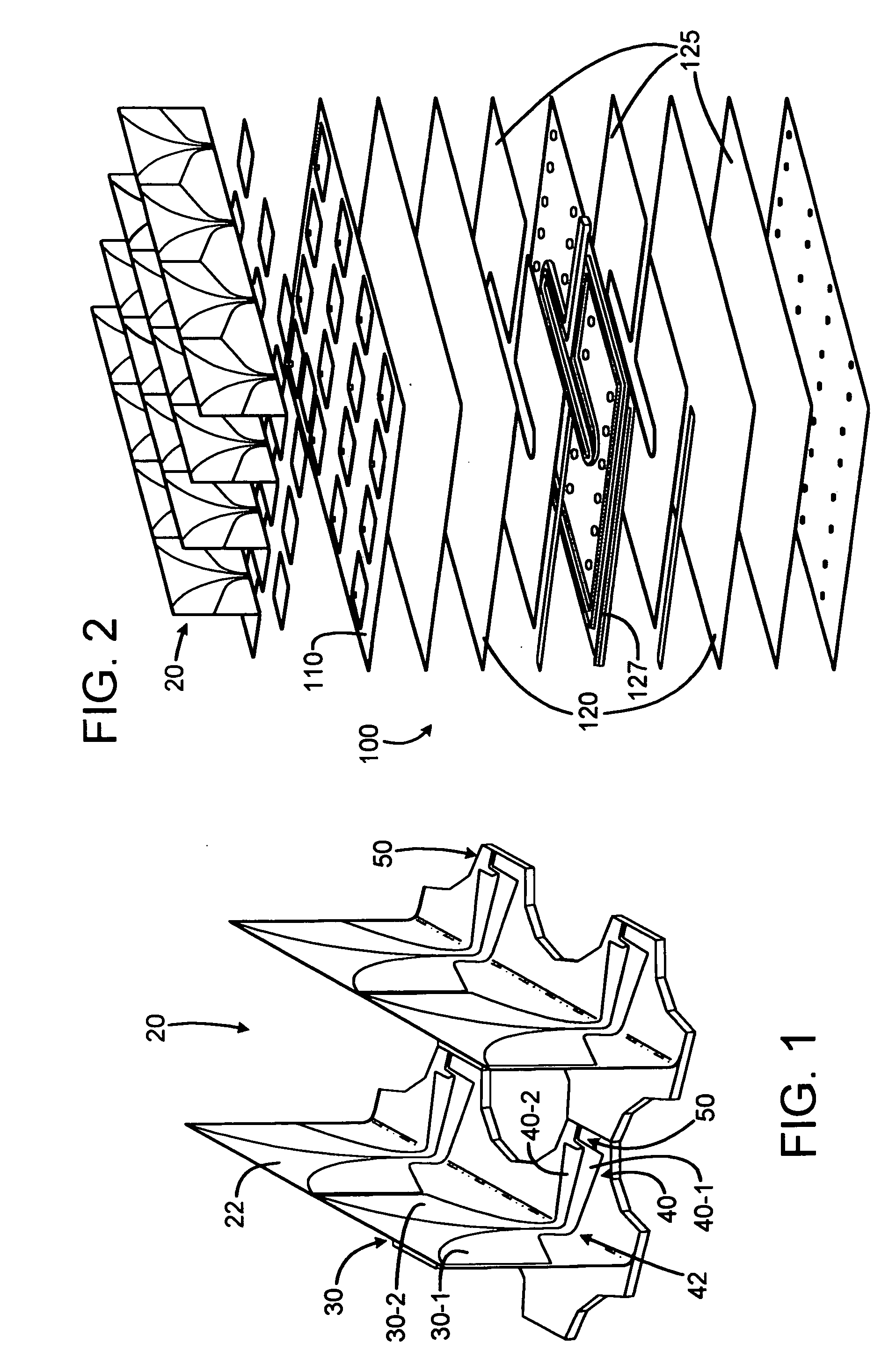
[0028] In an exemplary embodiment illustrated in FIG. 1, a radiator structure 20 includes radiator elements 30 similar to the flared dipole radiator described ...


PUM


Abstract

A foldable radiator assembly includes a flexible dielectric substrate structure having a radiator conductor pattern formed therein. The flexible substrate structure can be flexible for movement between a folded position and a deployed position, or can be fixed in position by dielectric structures. An excitation circuit excites the radiator conductor pattern with RF energy. Strips of the radiator assemblies can be used to form an array aperture.

Description

BACKGROUND [0001] Some active array apertures are under stringent weight and space constraints. For example, space-based arrays need to be delivered into space, and so there are stringent weight and space limitations imposed by the launch vehicle capabilities. Another exemplary application involves stowing an array for battlefield deployment, e.g., when such an array is carried by a weight-sensitive transport such as a soldier. [0002] There is a need for an array aperture that is relatively light weight. It would be an advantage to provide an array aperture which can be stored in a relatively small space. SUMMARY OF THE DISCLOSURE [0003] A foldable radiator assembly includes a thin, flexible dielectric substrate structure having a radiator conductor pattern formed therein. The flexible substrate structure is flexible for movement between a folded position and a deployed position. An excitation circuit excites the radiator conductor pattern with RF energy. [0004] Strips of the radiat...

Claims


Application Information

Patent Timeline
Patent Type & Authority Applications(United States)
IPC IPC(8): H01Q1/08H01Q1/38H01Q13/08
CPCH01Q1/085H01Q13/085H01Q1/38H01Q1/087
Inventor COX, GERALD A.HAUHE, MARK S.LIVINGSTON, STAN W.TALLMAN, COLLEENQUAN, CLIFTONREINEHR, ANITA L.ZHANG, YANMIN
Owner RAYTHEON CO
Why Eureka
Try Eureka