Image pick-up lens, image pick-up unit and mobile terminal

a technology for picking up lenses and mobile terminals, which is applied in the field of small-sized image picking up lenses, can solve problems such as under-correction of on-axial chromatic aberration

Inactive Publication Date: 2005-12-01
KONICA MINOLTA OPTO
View PDF5 Cites 48 Cited by
  • Summary
  • Abstract
  • Description
  • Claims
  • Application Information

AI Technical Summary

Benefits of technology

[0009] The present invention is attained in view of such a problem, and an object of the present invention is to provide an image pick-up lens of 3-lenses composition, in which, although it is a small sized one, aberrations are fine...

Problems solved by technology

However, although the image pick-up lenses disclosed in Patent Documents 1, 2, are types appropriate for the size reduction, because Abbe's number of a lens forming the negative third lens is more th...

Method used


Image

  • Image pick-up lens, image pick-up unit and mobile terminal
  • Image pick-up lens, image pick-up unit and mobile terminal
  • Image pick-up lens, image pick-up unit and mobile terminal

Examples


example 1

[0109] The lens of the image pick-up lens of the example 1 will be shown in Tables 1, 2. Hereupon, hereinafter (including the lens data of Table), the exponent of 10 (for example, 2.5×10−03) is expressed by E (for example, 2.5 E−03).

TABLE 1(Example 1)f = 4.76 mm, fB = 1.29 mm, F = 3.55, 2YD = 5.76 mmSurface No.R(mm)D(mm)Ndνd11.8331.151.5318056.022.4840.23stop∞0.633−2.9491.401.5318056.04−0.8650.435−1.1510.781.5830030.06−5.2360.507∞0.301.5163364.18∞

[0110]

TABLE 2Aspheric surface coefficientThe first surfaceK = 8.15240E−01A4 = 1.15670E−03A6 = 2.68720E−04A8 = −1.53710E−04A10 = 1.63690E−03A12 = −7.41830E−04The second surfaceK = 8.10010E+00A4 = 3.12300E−02A6 = −4.12710E−03A8 = 6.36510E−02A10 = −1.35200E−01The third surfaceK = 1.98740E+00A4 = −3.87450E−02A6 = −1.41830E−01A8 = 3.05260E−01A10 = −1.08580E−01The fourth surfaceK = −2.17580E+00A4 = −1.38170E−01A6 = 5.20030E−02A8 = −2.99170E−02A10 = −4.50210E−04A12 = 6.72390E−03The fifth surfaceK = −3.38230E+00A4 =−4.51040E−02A6 = 1.47580E−02A8 ...

example 2

[0112] The lens data of the image pick-up lens of Example 2 will be shown in Tables 3, 4.

TABLE 3(Example 2)f = 4.74 mm, fB = 1.18 mm, F = 3.55, 2YD = 5.76 mmSurface No.R(mm)D(mm)Ndνd1  1.7540.901.5318056.02  2.5510.23stop∞0.723−2.7751.311.5318056.04−0.9230.585−1.0600.771.5830030.06−3.4360.507∞0.301.5163364.18∞

[0113]

TABLE 4Aspheric surface coefficientThe first surfaceK = 1.00000E+00A4 = 3.83455E−03A6 = −7.74676E−03A8 = 7.04763E−03A10 = 4.19748E−03A12 = −3.78379E−03The second surfaceK = 7.31690E+00A4 = 3.82257E−02A6 = −2.24935E−02A8 = 2.03789E−01A10 = −2.05242E−01The third surfaceK = 1.37292E+00A4 = −4.84359E−02A6 = −1.47866E−01A8 = 2.24391E−01A10 = −5.66396E−02The fourth surfaceK = −2.33525E+00A4 = −1.60082E−01A6 = 5.67647E−02A8 = −2.67774E−02A10 = −2.06476E−03A12 = 5.81712E−03The fifth surfaceK = −2.47897E+00A4 = −2.61248E−02A6 = 1.68687E−02A8 = 2.40536E−04A10 = −5.42875E−04A12 = −3.87552E−05The sixth surfaceK = 1.05726E+00A4 = −8.69612E−04A6 = 5.23503E−03A8 = −7.44161E−04A10 = 5....

example 3

[0115] The lens data of the image pick-up lens of Example 3 will be shown in Tables 5, 6.

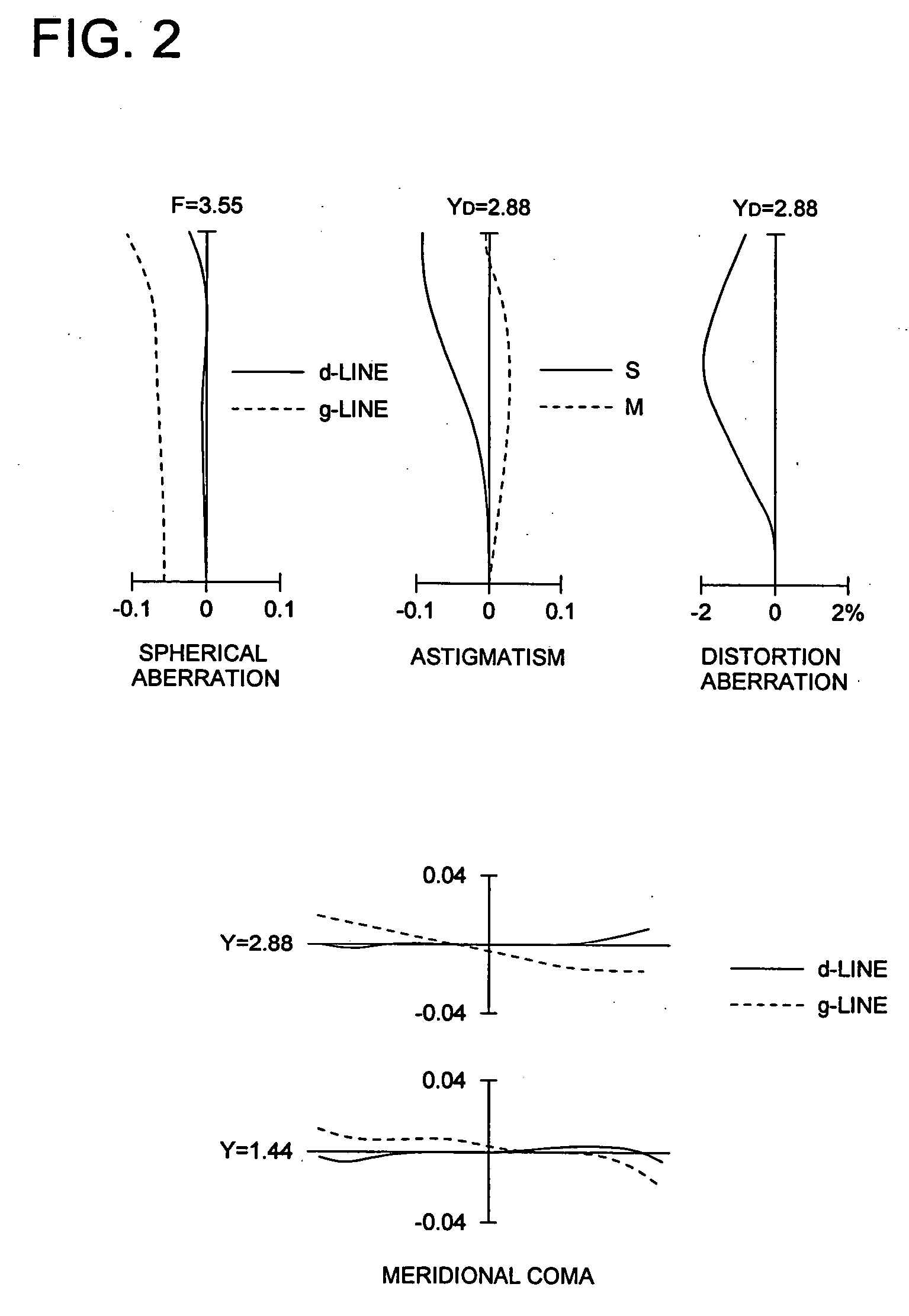
TABLE 5(Example 3)f = 4.74 mm, fB = 1.12 mm, F = 2.88, 2YD = 5.76 mmSurface No.R(mm)D(mm)Ndνd1  1.9341.141.5318056.02  3.5060.36stop∞0.453−2.1251.421.5318056.04−0.8920.615−0.8830.901.5830030.06−2.0560.507∞0.301.5163364.18∞

[0116]

TABLE 6Aspheric surface coefficientThe first surfaceK = 5.81620E−01A4 = −5.22970E−03A6 = 8.47900−03A8 = −7.49790E−03A10 = 3.56630E−03A12 = −6.40100E−04The second surfaceK = 8.25360E+00A4 = 7.27660E−03A6 = −1.45830E−02A8 = 2.20510E−02A10 = −1.99260E−02The third surfaceK = 4.60860E+00A4 = −5.66520E−02A6 = −4.85170E−02A8 = 9.20040E−02A10 = −2.08330E−01A12 = 2.31630E−01The fourth surfaceK = −2.20310E+00A4 = −1.23930E−01A6 = 1.83900E−02A8 = −1.58110E−02A10 = 5.35900E−03A12 = −3.34090E−03The fifth surfaceK = −2.93760E+00A4 = −9.77290E−03A6 = −2.42990E−03A8 = −2.61640E−04A10 = 4.09210E−04A12 = −2.42210E−05The sixth surfaceK = −8.38010E+00A4 = −2.46160E−02A6 = 2.81820E−03A8 = −...


PUM


Abstract

An image pick-up lens for forming an image of an object on a solid image pick-up element having a rectangular effective pixel area, has a first lens; a second lens; a third lens; and a diaphragm having an aperture. The following conditional expressions are satisfied:
15°<IAD<35°
|IAh−(IAD·Yh/YD)|<5°
where,
    • YD: a length of ½ of the diagonal length of the rectangular effective pixel area of the solid image pick-up element,
    • Yh: an arbitrary image height of the image pick-up lens (where, Yh<YD),
    • IAD: an angle formed between a chief ray of a light flux forming an image at the image height YD of the image pick-up lens and the optical axis, and
    • IAh: an angle formed between a chief ray of a light flux image forming an image at the image height Yh of the image pick-up lens, and the optical axis.

Description

[0001] This application is based on Japanese Patent Application No. 2004-157667 filed on May 27, 2004, in Japanese Patent Office, the entire content of which is hereby incorporated by reference. BACKGROUND OF THE INVENTION [0002] The present invention relates to a small sized image pick-up lens using a solid image pick-up element such as CCD type image sensor or CMOS type image sensor, image pick-up unit and mobile terminal provided therewith. [0003] Recently, following making into high performance and size reduction of an image pick-up apparatus using a solid image pick-up element such as CCD (Charge Coupled Device) type image sensor or CMOS (Complementary Metal Oxide Semiconductor) type image sensor, a mobile phone or personal computer provided with the image pick-up apparatus is spreading. Further, for an image pick-up lens mounted in these image pick-up apparatus, a requirement for the further size reduction is increased. [0004] As an image pick-up lens for such an application, ...

Claims


Application Information

Patent Timeline
IPC IPC(8): G02B13/00H04N5/225H04N5/232
CPCH04N5/2254H04N23/55
Inventor YAMAGUCHI, SUSUMUISONO, MASASHI
Owner KONICA MINOLTA OPTO
Why Eureka
Try Eureka