Apparatus for providing a pattern of polarization

a technology of polarization pattern and apparatus, applied in the field of optical systems, can solve the problems of undesired intensity variation, difficult and expensive creation of such polarization pattern, complicated and difficult to manufacture mosaic tiles, etc., and achieve the effect of simple structure and easy generation of polarization pattern

Inactive Publication Date: 2005-12-01
ASML HLDG NV
View PDF14 Cites 85 Cited by
  • Summary
  • Abstract
  • Description
  • Claims
  • Application Information

AI Technical Summary

Benefits of technology

[0012] According to a further feature, one or more beam shapers, such as, a diffractive optical element or mask, can be provided on a common optical before or after a polarization pattern assembly. A beam shaper in combination with the polarization pattern assembly can further facilitate the generation of polarization patterns according to the present invention.
[0013] An advantage of embodiments of the present invention is that a polarization pattern assembly with a polarization pane can have a relatively simple structure yet is versatile. Such a polarization pattern assembly can produce a variety of polarization patterns by simply rotating the polarization pattern assembly relative to an incident beam, by rotating the direction of polarization of an incident beam, or by adding or modify a beam shaper.
[0015] A further advantage is realized for polarized illuminators in lithography as embodiments of the present invention can allow for a variety of polarization patterns at a particular pupil of interest.

Problems solved by technology

However, only parallel components of the electric field generally can interfere, so the polarization state of each ray at the wafer affects the coherent imaging.
Heretofore, creating such polarization patterns has been difficult and expensive.
This mosaic of tiles is complicated and difficult to manufacture.
This is disadvantageous as differential thermal expansion across the mosaic, especially in natural birefringent crystal material, can prevent optical contact and lead to apodization (i.e. undesired intensity variations) at the pupil.

Method used


Image

  • Apparatus for providing a pattern of polarization
  • Apparatus for providing a pattern of polarization
  • Apparatus for providing a pattern of polarization

Examples


Embodiment Construction

[0025] Reference will now be made to the drawings in which the various elements of the present invention will be given numerical designations and in which the invention will be discussed so as to enable one skilled in the art to make and use the invention.

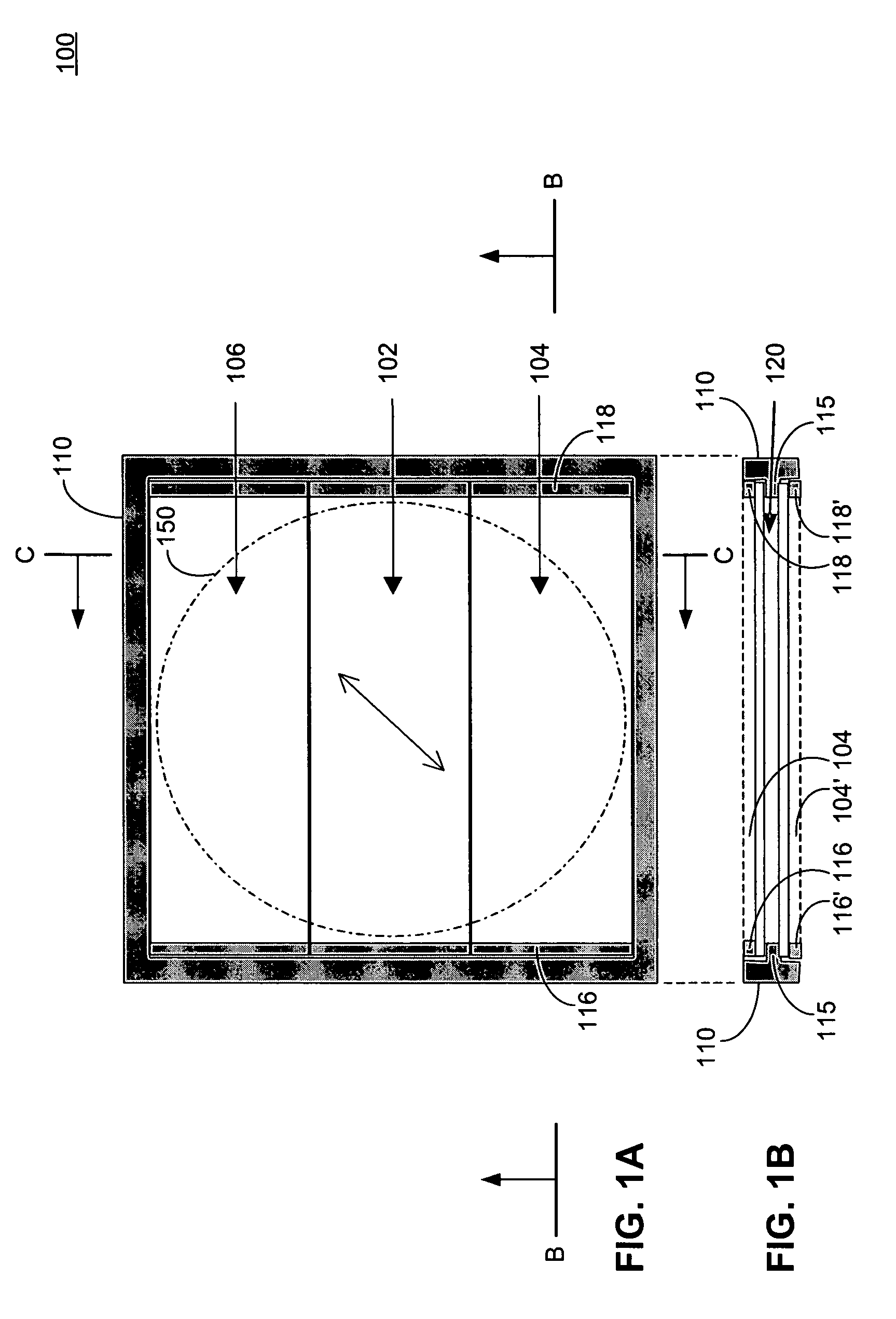
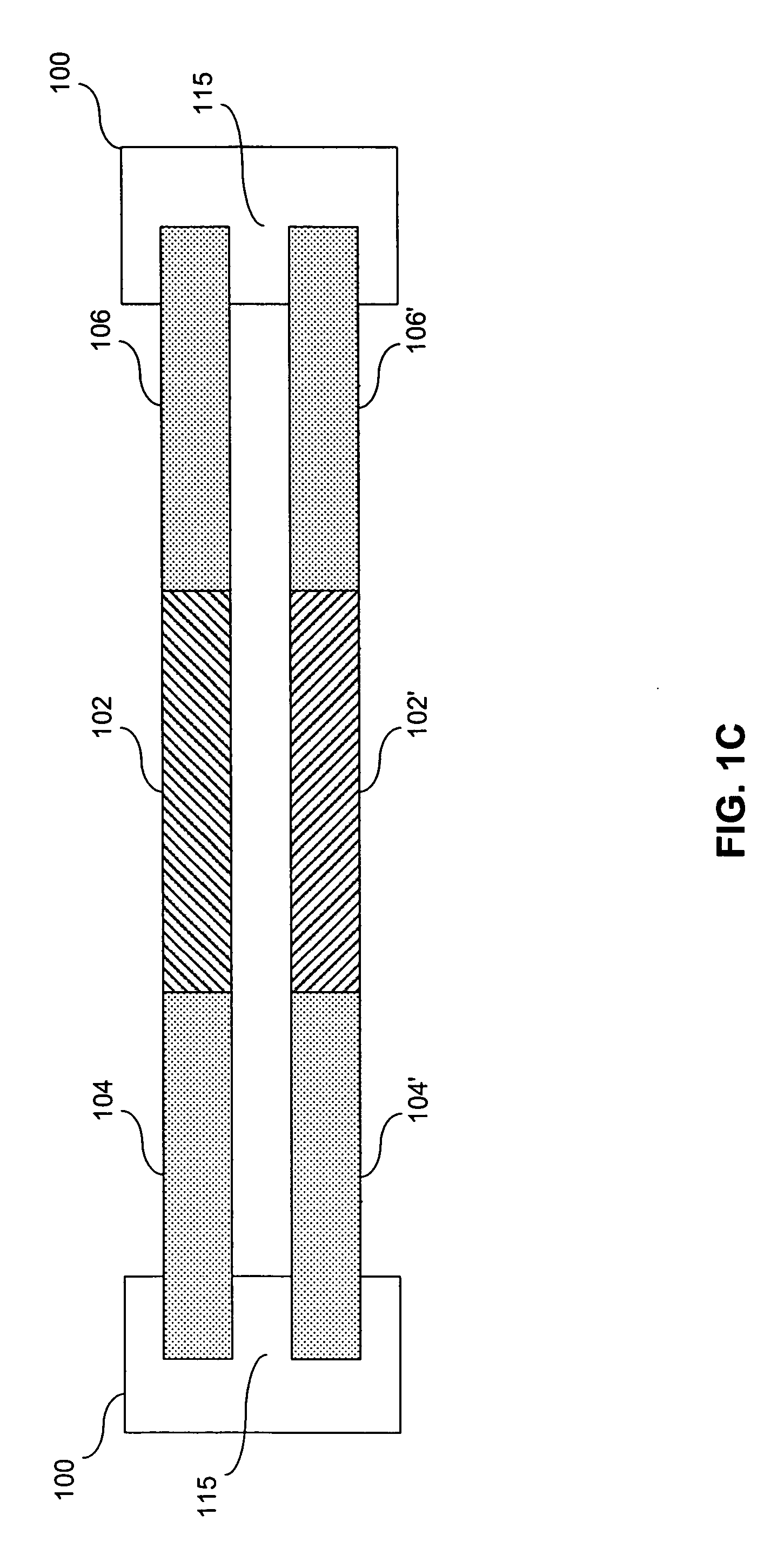
[0026]FIGS. 1A-1C are diagrams of a polarization pattern assembly 100 according to an embodiment of the present invention. As shown in FIG. 1A, polarization pattern assembly 100 includes a frame 110 that holds polarization pane 102 in a central region of frame 110. Frame 110 can further hold two non-polarization panes 104 and 106 on opposite sides of polarization pane 102 in a first layer. As shown in FIGS. 1B and 1C, frame 110 can also hold a second layer having a polarization pane 102′ in between non-polarization panes 104′ and 106′ in a stack arrangement below respective panes 102-106 of the first layer.

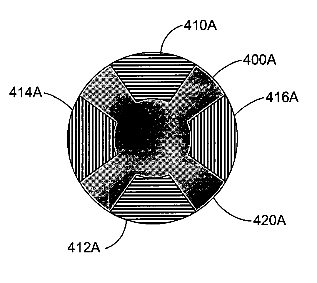
[0027] Polarization panes 102, 102′ can rotate the direction of polarization of light incident on the panes. For example, pol...


PUM

PropertyMeasurementUnit
birefringentaaaaaaaaaa
non-birefringentaaaaaaaaaa
sizeaaaaaaaaaa

Abstract

The present invention relates to polarization pattern illumination. A polarization pattern assembly produces a polarization pattern. In an embodiment, a polarization pattern assembly includes a frame that supports a polarization pane in a central region of the frame. The polarization pane changes the polarization direction of light incident upon the polarization pane. Different polarization patterns in a pupil of a polarized illuminator can be generated.

Description

FIELD OF THE INVENTION [0001] The present invention relates to optical systems that provide light beams with polarization that varies along the cross section of the beam. BACKGROUND OF THE INVENTION BACKGROUND ART [0002] In order to create faster and more sophisticated circuitry, the semiconductor industry continually strives to reduce the size of the circuit elements. The circuits are produced primarily by photolithography. In this process, the circuits are printed onto a semiconductor substrate by exposing a coating of radiation sensitive material to light. The radiation sensitive material is often referred to as a “photoresist” or just resist. Passing the light through a mask, which may consist of a pattern of chrome or other opaque material formed on a transparent substrate, generates the desired circuit pattern. The mask may also be formed by a pattern of higher and lower regions etched into the surface of a transparent substrate, or some combination of the two techniques. Subs...

Claims


Application Information

Patent Timeline
Patent Type & Authority Applications(United States)
IPC IPC(8): G02B5/30G02B27/28G03F7/20
CPCG02B1/02G02B1/06G03F7/70566G02B5/3025G02B27/286G02B1/08H01L21/027
Inventor ALBERT, MICHAEL M.
Owner ASML HLDG NV
Why Eureka
Try Eureka