Lens driving device and imaging device

a driving device and lens technology, applied in the field of lenses driving devices and imaging devices, can solve the problems of insufficient imaging function and image quality of images, large space limitations of lens and ccd components, and the use of lenses and ccds is limited to taking pictures or images, so as to reduce the cost and space necessary to provide the new component for securing the imaging element to the body enclosure and other problems, to avoid image shifting, reduce the effect of the entire device and the effect of reducing

Inactive Publication Date: 2005-12-01
FUJI PHOTO OPTICAL CO LTD
View PDF13 Cites 14 Cited by
  • Summary
  • Abstract
  • Description
  • Claims
  • Application Information

AI Technical Summary

Benefits of technology

[0030] According to the lens driving device of this embodiment, inside the cylindrical shape of the stator, the rotor and lens holder are arranged. Further, the imaging element is held by the cover which covers the cylindrical mouth of the cylindrical shape of the stator on the side opposite to an incident side of the object light. For this reason, while cost and space necessary to provide the new component for securing the imaging element to the body enclosure and others are reduced, the relative positions of the lenses and the imaging element to each other can be fixed, thereby avoiding image shifting occurring on the picked up image.
[0031] Further, in the lens driving device according to this embodiment, the rotor, lens hold

Problems solved by technology

However, since the imaging device incorporated in these small-sized devices such as the cellular phone is much smaller than an ordinary digital camera, the size of its components such as a lens and CCD (Charge Coupled Device) and the space for housing these components are greatly limited.
Thus, in order that these small-sized devices are used in place of the digital camera, they are insufficient in the imaging function and image quality of the image.
Their use is limited to taking a picture or image not requiring image quality, e.g. taking the picture in place of making a note, or taking the picture fo

Method used


Image

  • Lens driving device and imaging device
  • Lens driving device and imaging device
  • Lens driving device and imaging device

Examples


Embodiment Construction

[0045] Now referring to the drawings, an explanation will be given of various embodiments of this invention.

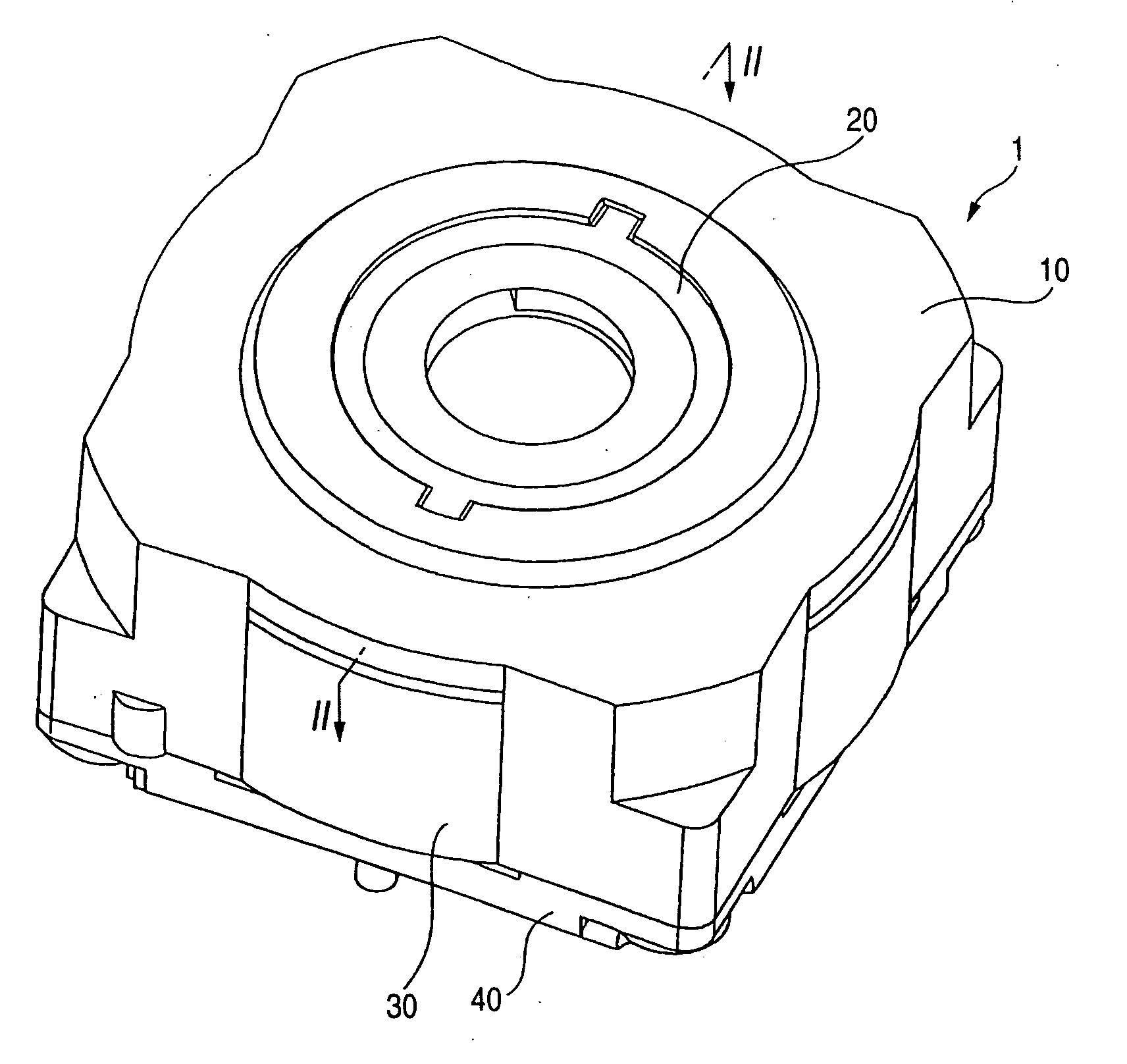
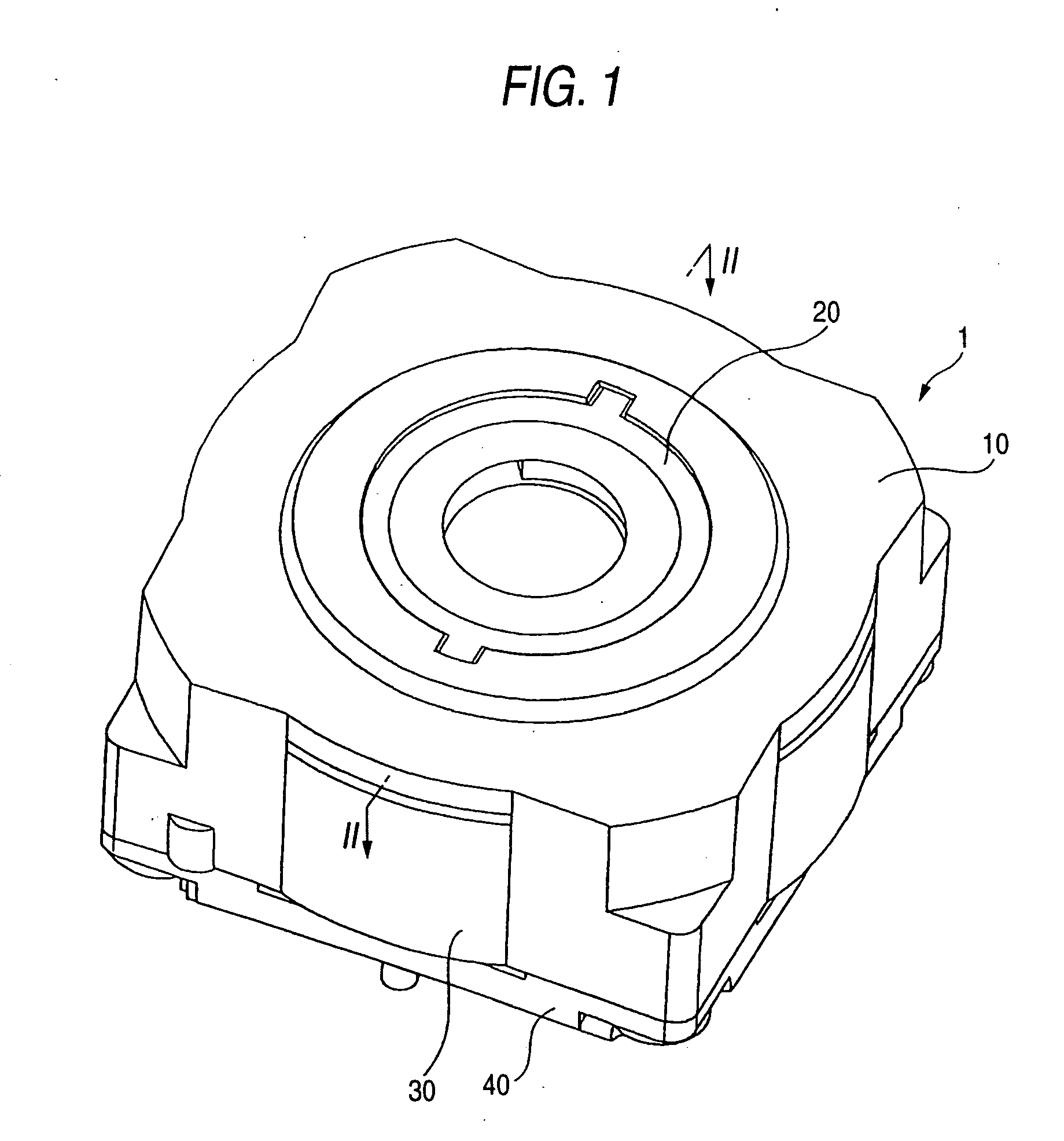
[0046]FIG. 1 is an appearance perspective view of the imaging device to which an embodiment of this invention is applied.

[0047] An imaging device 1 is a small-sized imaging device incorporated in e.g. a cellular phone, which has an auto-focusing function of focusing on an object by driving a plurality of lenses in direction along the optical axis (hereinafter referred to as a back-and-forth direction). In the imaging device 1, in its external appearance, a stator 30 having a cylindrical shape is sandwiched between an upper cover 10 and a lower cover 40. Inside the stator 30, a magnet and lenses described later are arranged. Apart of the front of lens holder 20 which holds the lenses is engaged with a part of the upper cover 10.

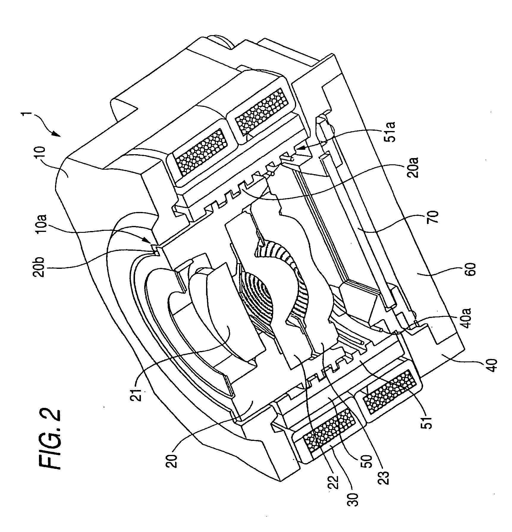
[0048]FIG. 2 is a sectional view taken in line II-II in the imaging device shown in FIG. 1.

[0049] In FIG. 2 illustrated are the upper cover 10, lowe...


PUM


Abstract

A lens driving device includes: a stator having a cylindrical shape, for generating a magnetic field within the cylindrical shape; a rotor located within the cylindrical shape of the stator and being rotation-driven for the stator by a magnetic field created by the stator; a lens holder located further inside the rotor, for holding a plurality of lenses with a small lens thereof being located at an arrangement end of the plurality of lenses; a converting mechanism for converting the direction of force by rotation driving of the rotor into direction along the optical axes of the lenses and transmitting the force in the direction thus converted to the lens holder; and a rotation stopper mechanism formed beside the small lens, for preventing the rotation of the lens holder through physical contact.

Description

BACKGROUND OF THE INVENTION [0001] 1. Technical Field of the Invention [0002] This invention relates to a lens driving device for driving lenses in a direction along their optical axes, and an imaging device for acquiring image data representing object light. [0003] 2. Description of the Related Art [0004] It is now prevalent that an imaging device for acquiring a digital image of an object is incorporated in small-sized devices such as a cellular phone and PDA (Personal Digital Assistant). Since the small-sized device a user always carries is equipped with the imaging device, the user can easily take a photograph at any time without labor of carrying a digital camera or video camera. These small-sized devices, which usually previously incorporate a data communication function using radio wave or infrared rays, has an advantage of capable of instantaneously, on the spot, transmitting a picked up image to another cellular phone or a personal computer. [0005] However, since the imagin...

Claims


Application Information

Patent Timeline
IPC IPC(8): G02B7/08G02B7/10G02B13/00H04N5/225
CPCH04N5/2254G02B7/102H04N23/55
Inventor MANABE, MITSUO
Owner FUJI PHOTO OPTICAL CO LTD
Why Eureka
Try Eureka