
Extruded strut, fuselage and front wing assembly for towable hydrofoil

a technology of towable hydrofoil and fuselage, which is applied in the direction of recreational vessels, special-purpose vessels, vessel construction, etc., can solve the problems of poor finish, a lot of grinding, sanding and machining of cast parts, and many small voids

Active Publication Date: 2005-12-01
MURPHY MICHAEL J
View PDF40 Cites 22 Cited by
  • Summary
  • Abstract
  • Description
  • Claims
  • Application Information

AI Technical Summary

Benefits of technology

[0005] Another advantage to extruding the strut is that it allows for the ready shortening or lengthening of the strut t...

Problems solved by technology

This requires a lot of grinding, sanding and machining of the cast part after it has been taken out of the mold.
Another disadvantage in manufacturing using the cast process is that the metal as it cures releases or gives off gases, resulting in the production of many small voids.
This porosity in the part results in a poor finish.
In addition as the casting comes out of the mold, there is shrinkage and the extent of the shrinkage is variable due to the nature of the alloy and weather conditions during the curing process.
The primary disadvantage of a part cast from 356A aluminum is that it does not have the ability to flex which can result in a catastrophic failure or breakage of the part.
There is a large rejection rate when casting an aluminum part due to the temperature of the mold, the outside temperature, and the amount of the metal as it is poured into the mold.
There is a lack of overall consistency in the parts.
The surface porosity of the cast part adds drag to the foil assembly, which hinders the performance of the hydrofoil assembly.
The porosity of the cast part also is not compatible with and does not accept the anodizing process.
This process wastes a lot of metal and also requires a lot of machine time.
For example, if the billet has been ground and machined so that the grain runs in the same direction as the long dimension of the strut, this means that the grain runs crosswise, across the short or lateral dimension of the fuselage in which case the strut is quite strong and break resistant when towed through the water since the force is mainly across the grain while at the same time, the fuselage is relatively weak and subject to failure since the elongate fuselage when towed at high speed is subject to powerful lateral forces when the fuselage becomes out of alignment with the direction of the tow (which is often the case).
When the fuselage lands from a jump, the forces of the water pressure on the wings and wing bolt holes often result in breakage.

Method used


Image

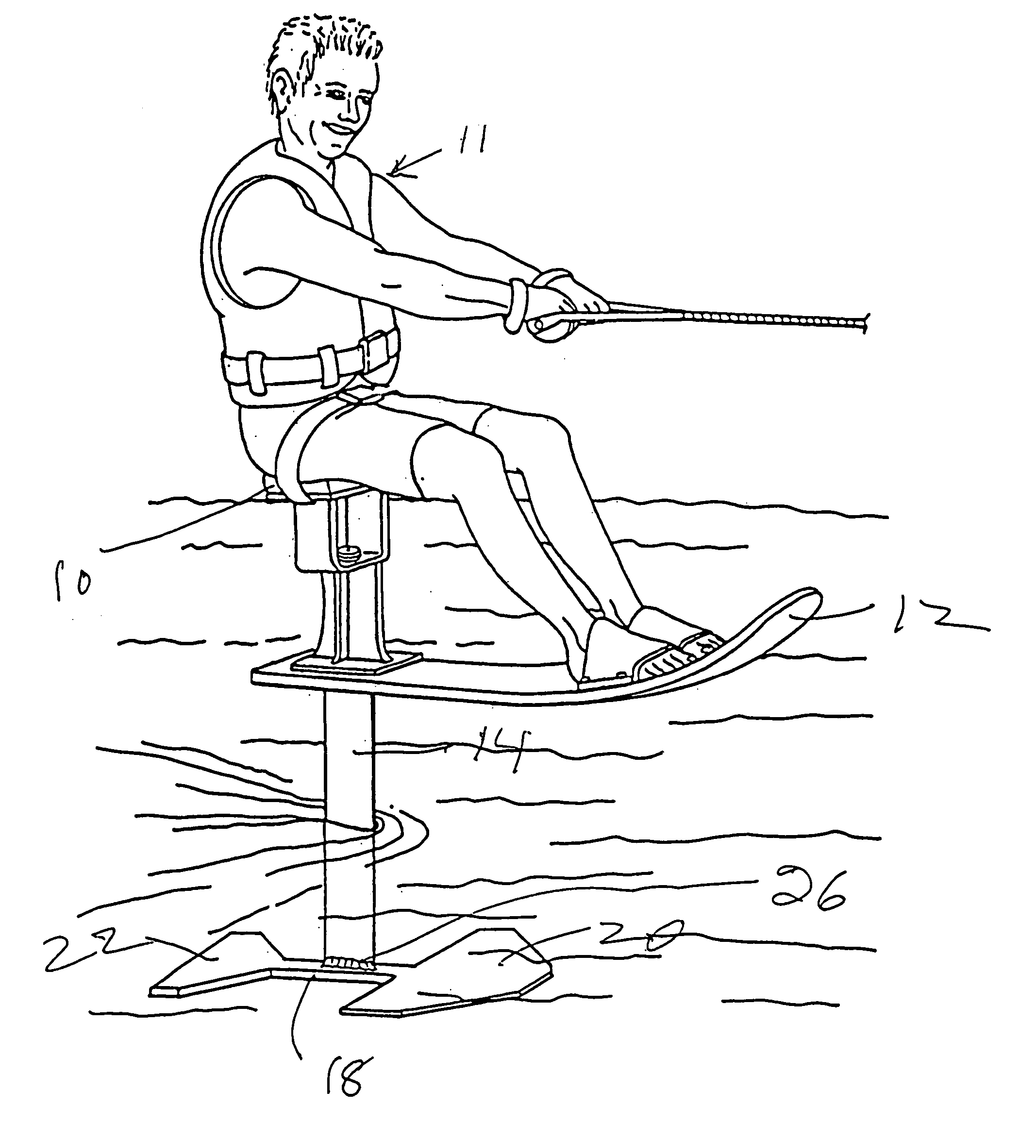
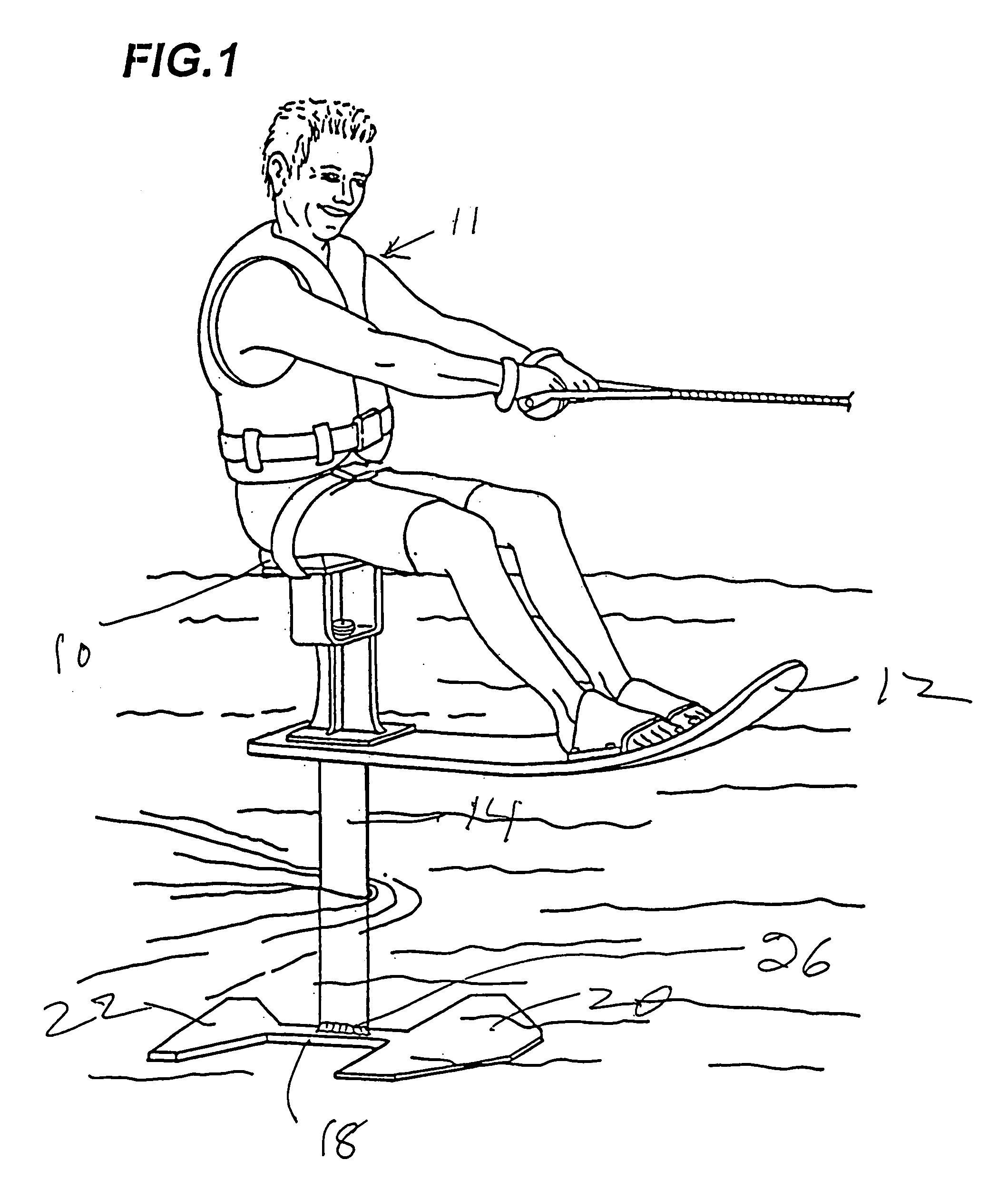
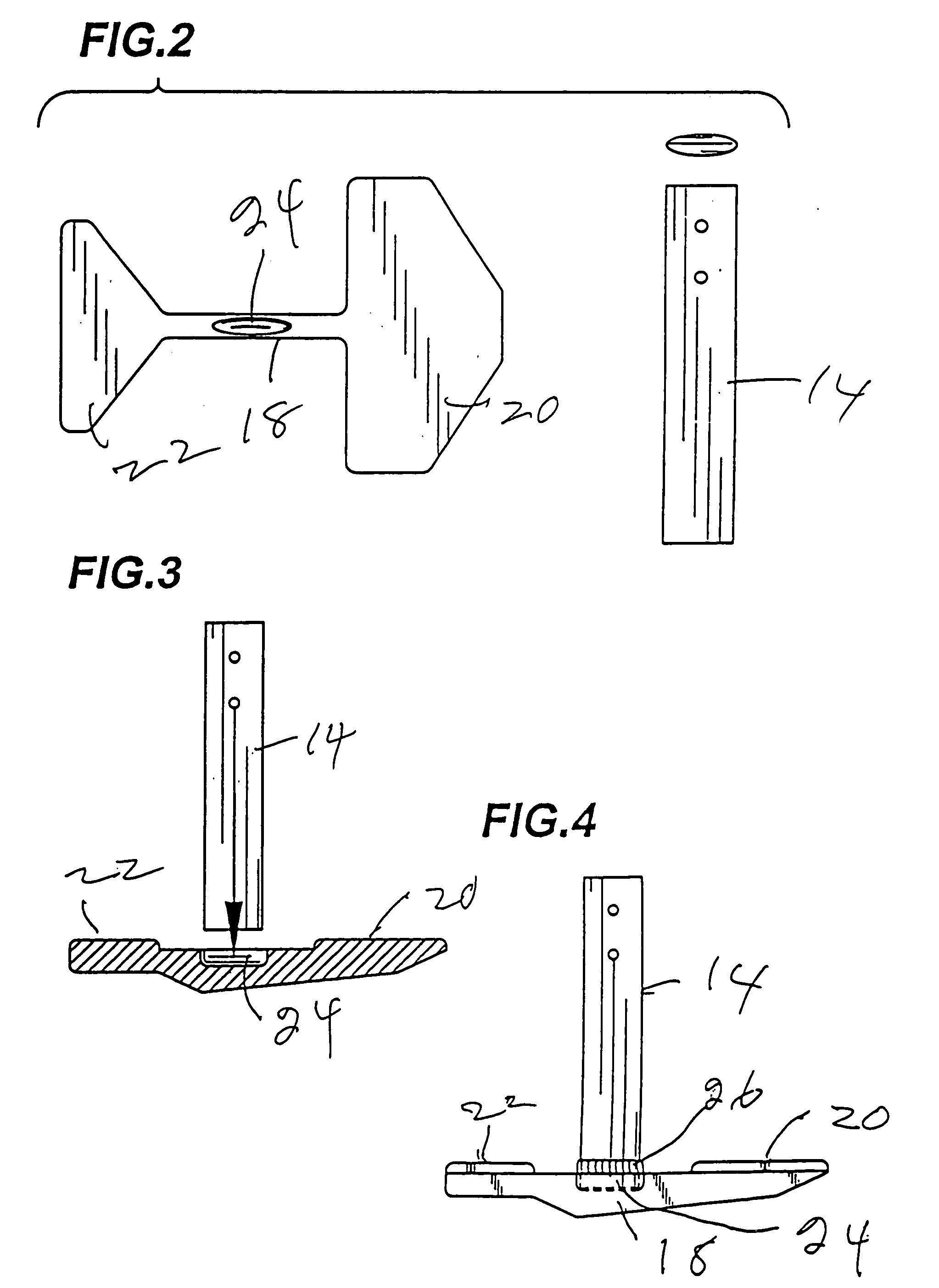
  • Extruded strut, fuselage and front wing assembly for towable hydrofoil
  • Extruded strut, fuselage and front wing assembly for towable hydrofoil
  • Extruded strut, fuselage and front wing assembly for towable hydrofoil

Examples


Embodiment Construction

[0014] The water sport device of this invention may be of the sit on type as variously described in the above-mentioned patents. The water sport device can also be without a seat for the rider in which case the rider either stands upright on the board, or kneels or lays on the board as it is towed. Foot and / or hand holders may be provided at appropriate locations (which are known to those skilled in the art) on the upper surface of the board to enable the rider to hang on as the board is towed.

[0015] Turning to that embodiment which is of the sit-on type:

[0016] The means for towing the towable water sport devices of this invention are not part of the invention. The towable water sport devices can be towed by a number of means including a powerboat, various kites of the type used to tow kiteboards (many of these are described at www.kiteboard.com), or by a helicopter.

[0017] The invention is applicable to extruded aluminum or aluminum alloy.

[0018] The invention preferably uses an ...


PUM


Abstract

A towable water sports device having a hydrofoil assembly including a strut, fuselage and front and rear blades carried by the fuselage wherein said parts are extruded aluminum or aluminum alloy.

Description

[0001] This patent application is a continuation-in-part of U.S. patent application Ser. No. 10 / 897,363 filed Jul. 21, 2004, which in turn, claims the benefit of Provisional Patent Application Ser. No. 60 / 524,657, filed Nov. 25, 2003.BACKGROUND OF INVENTION [0002] Towable hydrofoil water sports devices for supporting a human rider are described in U.S. Pat. No. 5,100,354, granted Mar. 31, 1992, U.S. Pat. No. 5,249,998, granted Oct. 5, 1993, U.S. Pat. No. 6,179,676, Jan. 30, 2001, and U.S. Pat. No. 6,551,158, granted Apr. 22, 2003 [0003] These towable water sports devices have a strut, fuselage and front and rear wings or blades which are made by casting a molten aluminum alloy. This process requires pouring molten aluminum into a sand or steel mold. The alloy used in this process is, for example, a 356A aluminum which is then heat-treated to T-6 hardness. The casting is then ground or sanded down to eliminate all entry gates, all venting gates and the receiving canals. This requires...

Claims


Application Information

Patent Timeline
IPC IPC(8): B63B1/00B63B1/16B63B1/24B63B35/73B63B35/81B63B35/85B64D27/00
CPCB63B1/16B63B1/242B63B35/85B63B35/81B63B35/815B63B35/73B63B34/40B63B34/60
Inventor MURPHY, MICHAEL J.
Owner MURPHY MICHAEL J
Learn More