Intervertebral Implant

a technology of intervertebral implants and implants, which is applied in the field of intervertebral implants, can solve the problems of presenting the risk of injury, difficulty in insertion, and difficulty, and achieve the effect of reducing the minimum structural height and facilitating the placement of the intervertebral implan

Inactive Publication Date: 2005-12-01
CENTINEL SPINE LLC
View PDF101 Cites 219 Cited by
  • Summary
  • Abstract
  • Description
  • Claims
  • Application Information

AI Technical Summary

Benefits of technology

[0007] It is the object of the invention to embody an intervertebral implant of this generic type in such a way that the minimum structural height is reduced, to make it easier to insert the intervertebral implant into the intervertebral space.

Problems solved by technology

This is particularly difficult if an additional pivot insert is also embedded between the upper part and the lower part, as is the case in the known intervertebral implant of U.S. Pat. No. 5,314,477.
But even in two-piece intervertebral implants, difficulties also arise, especially if the implants also have pins and other protrusions on their support faces that are intended for anchoring the intervertebral implant in the bone.
Not only is this difficult, but it also presents the risk of injuries.
Since the intervertebral space has a relatively low height, it is also difficult for engagement elements that a manipulation instrument can engage to be secured to both parts of the intervertebral implant.
This dictates a minimum structural height for the upper part and for the lower part, and in conventional intervertebral implants, the structural heights of the upper part and lower part are thus added together, so that even if the upper and lower parts rest directly on one another, a relatively great structural height of the intervertebral implant is still unavoidable.

Method used


Image

  • Intervertebral Implant
  • Intervertebral Implant
  • Intervertebral Implant

Examples


Embodiment Construction

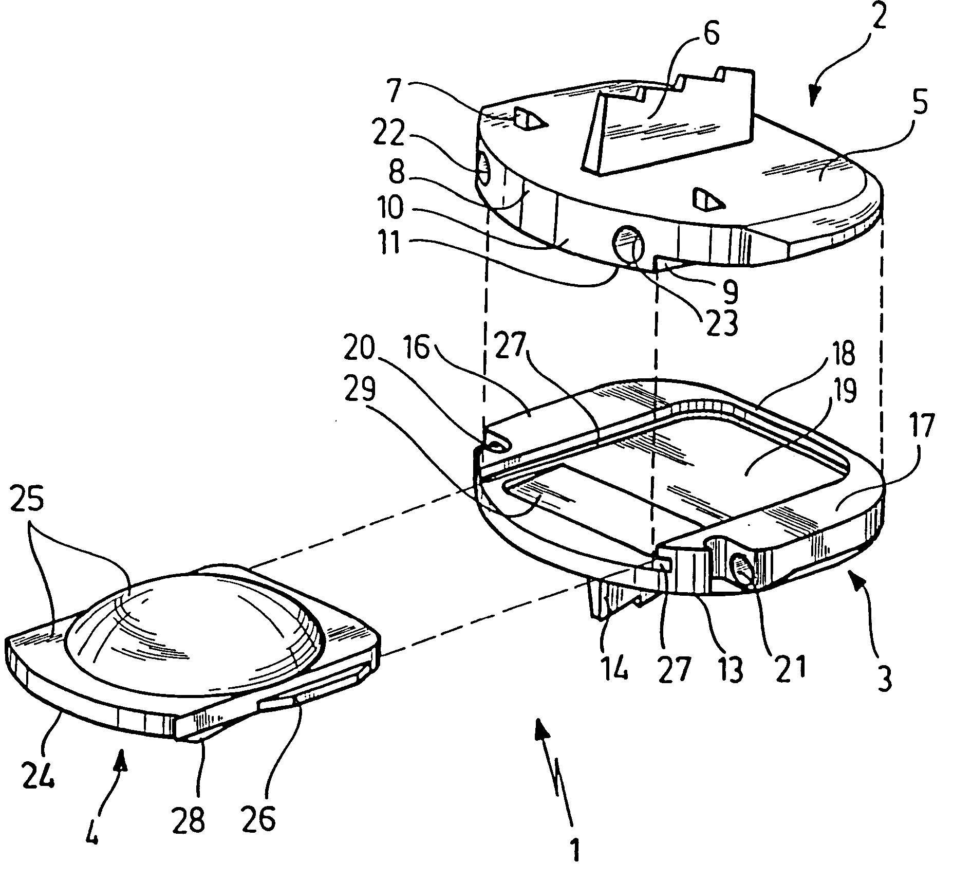
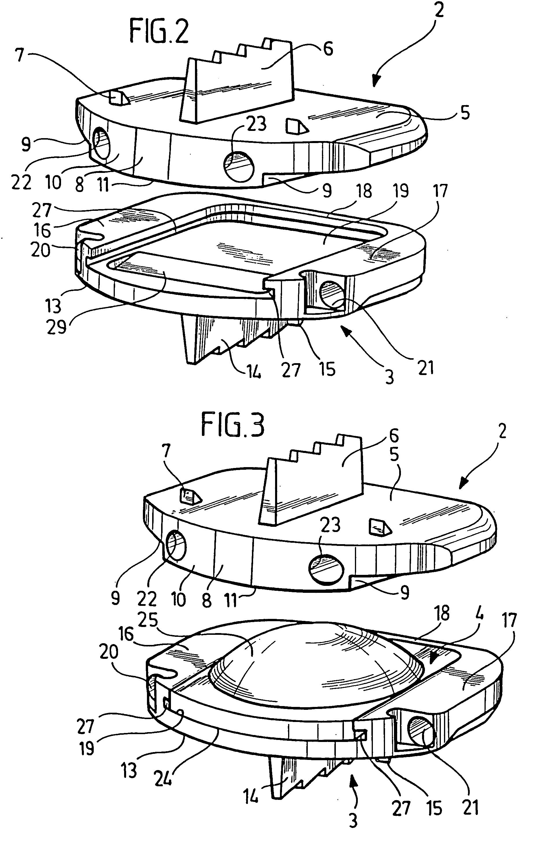
[0035] The intervertebral implant 1 shown in the drawing includes three parts, namely a platelike upper part 2, a platelike lower part 3, and a substantially platelike pivot insert 4.

[0036] The upper part 2 is embodied flat on its top, thus creating a support face 5, on which various kinds of protrusions 6, 7 are disposed which serve the purpose of anchoring the upper part 2 in a vertebra that rests, with its end face toward an intervertebral space, on the support face 5.

[0037] The upper part 2 is substantially rectangular in cross section; in the exemplary embodiment shown, a longitudinal edge 8 curves outward.

[0038] On the two short sides of this rectangle, the thickness of the platelike upper part 2 is less than in the central region, so that along the short sides of the upper part 2, downward-pointing recesses 9 each extending parallel to these edges are formed that are open toward the outside. The central region of the upper part 2 is located between the two recesses 9 and t...


PUM


Abstract

An intervertebral implant comprises first and second parts having outer surfaces engaging adjacent vertebral surfaces. An insert between these parts provides relative movement therebetween. The first and / or second parts may have engagement means in the form of apertures for engagement with insertion instruments. The first and second parts may nest together, in the absence of the insert, for insertion into the intervertebral space. The boundaries of the implant may form a working space which would include insertion instruments therein. A detent and detent recess may be provided for engagement of the insert and one of said first and second parts.

Description

[0001] This application is a continuation of U.S. application Ser. No. 10 / 018,402, now pending.BACKGROUND OF THE INVENTION [0002] The invention relates to an intervertebral implant, having an upper part that has a support face for a vertebra and a lower part that has a support face for an adjacent vertebra, on each of which parts engagement elements, which are accessible from one side of the intervertebral implant, for a manipulation instrument are disposed, in order to minimize the structural height of the intervertebral implant upon insertion into an intervertebral space. [0003] One such intervertebral implant is known for instance from U.S. Pat. No. 5,314,477. This intervertebral implant is used to replace a disk removed from the intervertebral space, and accordingly the intervertebral implant must have a relatively low structural height, since it has to fit into the gap between vertebrae. This is particularly difficult if an additional pivot insert is also embedded between the u...

Claims


Application Information

Patent Timeline
Patent Type & Authority Applications(United States)
IPC IPC(8): A61B17/00A61B17/02A61B17/56A61F2/00A61F2/30A61F2/44A61F2/46
CPCA61B17/025A61F2/44A61F2/4425A61F2/4611A61F2002/30131A61F2002/30138A61F2002/30324A61F2002/30383A61F2002/30504A61F2002/30604A61F2002/30662A61F2002/30808A61F2002/30848A61F2002/30884A61F2002/30892A61F2002/30904A61F2002/443A61F2220/0025A61F2230/0013A61F2230/0017A61F2250/0036A61F2310/00023A61F2/442A61F2/30767A61F2002/305A61F2002/30845A61F2002/30878A61F2002/30879A61F2002/30331A61F2/30749A61F2002/3065A61F2002/3093
Inventor MARNAY, THIERRYBEYERSDORFF, BORIS
Owner CENTINEL SPINE LLC
Why Eureka
Try Eureka