Electronic directing system

a technology of electronic directing system and navigation control system, which is applied in the direction of process and machine control, distance measurement, instruments, etc., can solve problems such as wear along the surface area

Active Publication Date: 2005-12-01
HUSQVARNA AB
View PDF13 Cites 51 Cited by
  • Summary
  • Abstract
  • Description
  • Claims
  • Application Information

AI Technical Summary

Problems solved by technology

Despite this fact, such products have only in recent years reached the market.
A disadvantage with the previous loop system is that the robot follows a laid down loop in order to direct the robot towards a certain place, which can be represented by a charging station for the robot's batteries and / or parking place for when the robot is not working.
A further disadvantage is that present types of navigational control stations normally direct the robot along a path, which is repeated each time the robot is directed.
Thereby the robot's wheels will cause wear along the surface area they pass.

Method used


Image

  • Electronic directing system
  • Electronic directing system
  • Electronic directing system

Examples


Embodiment Construction

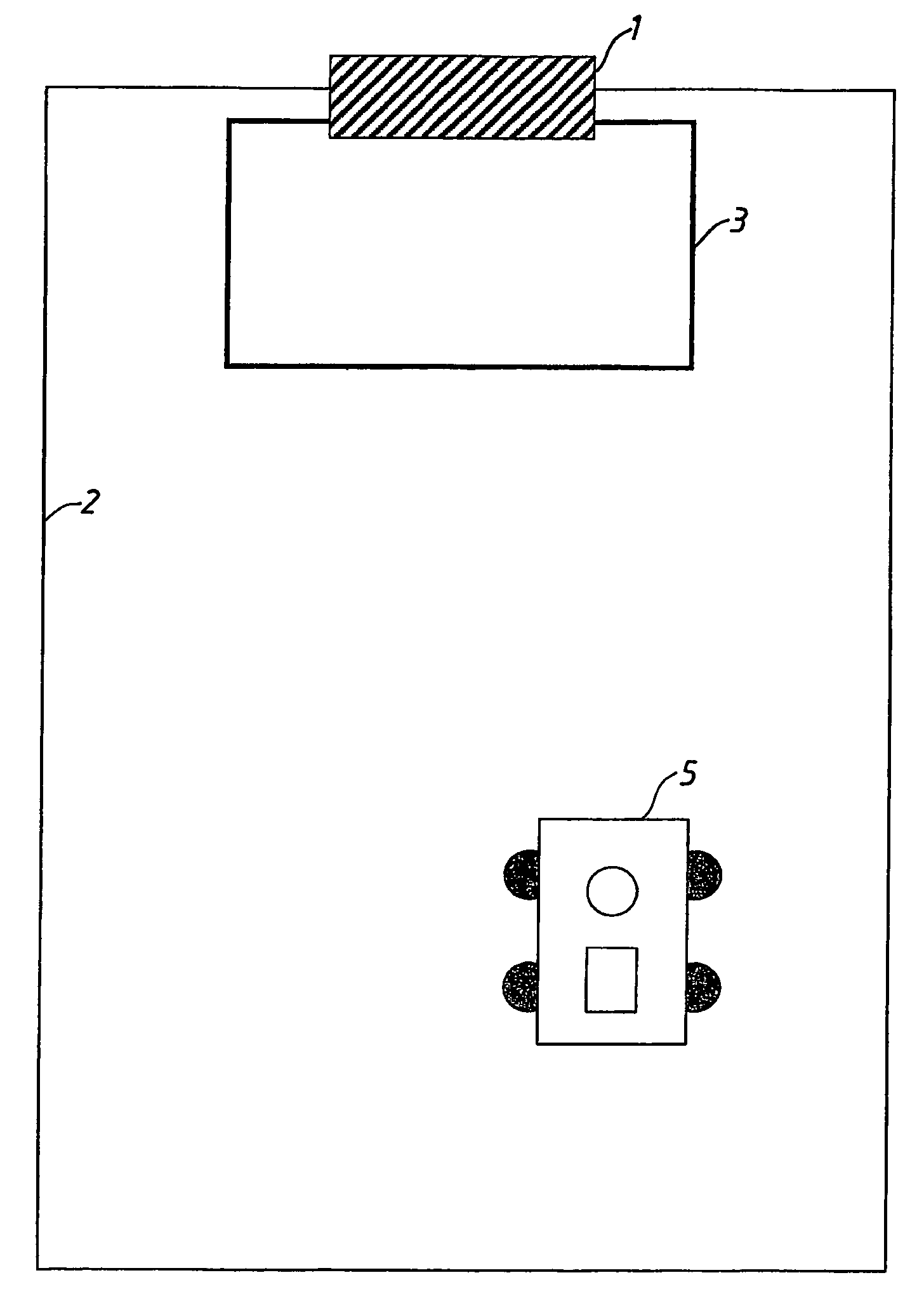
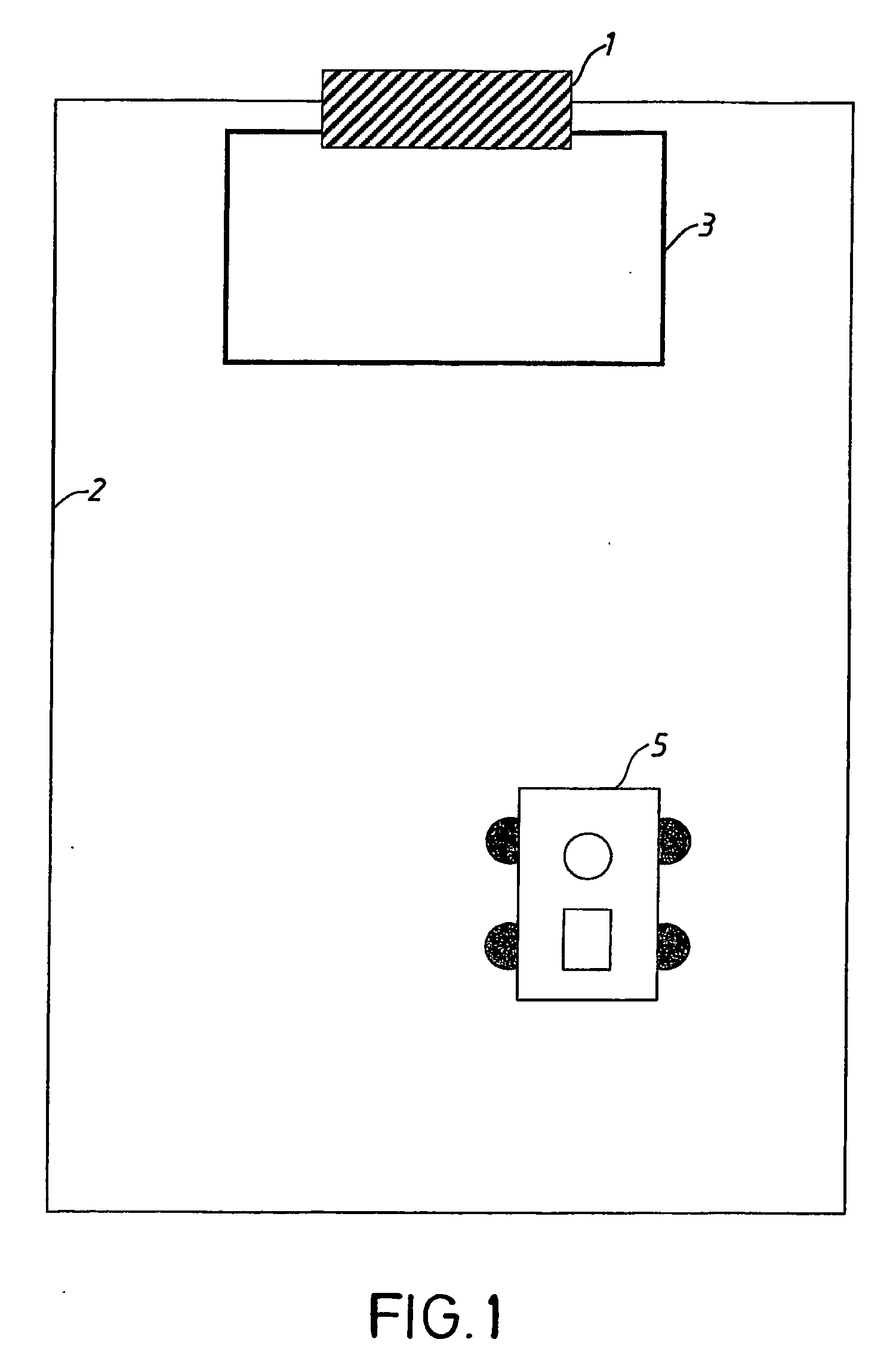
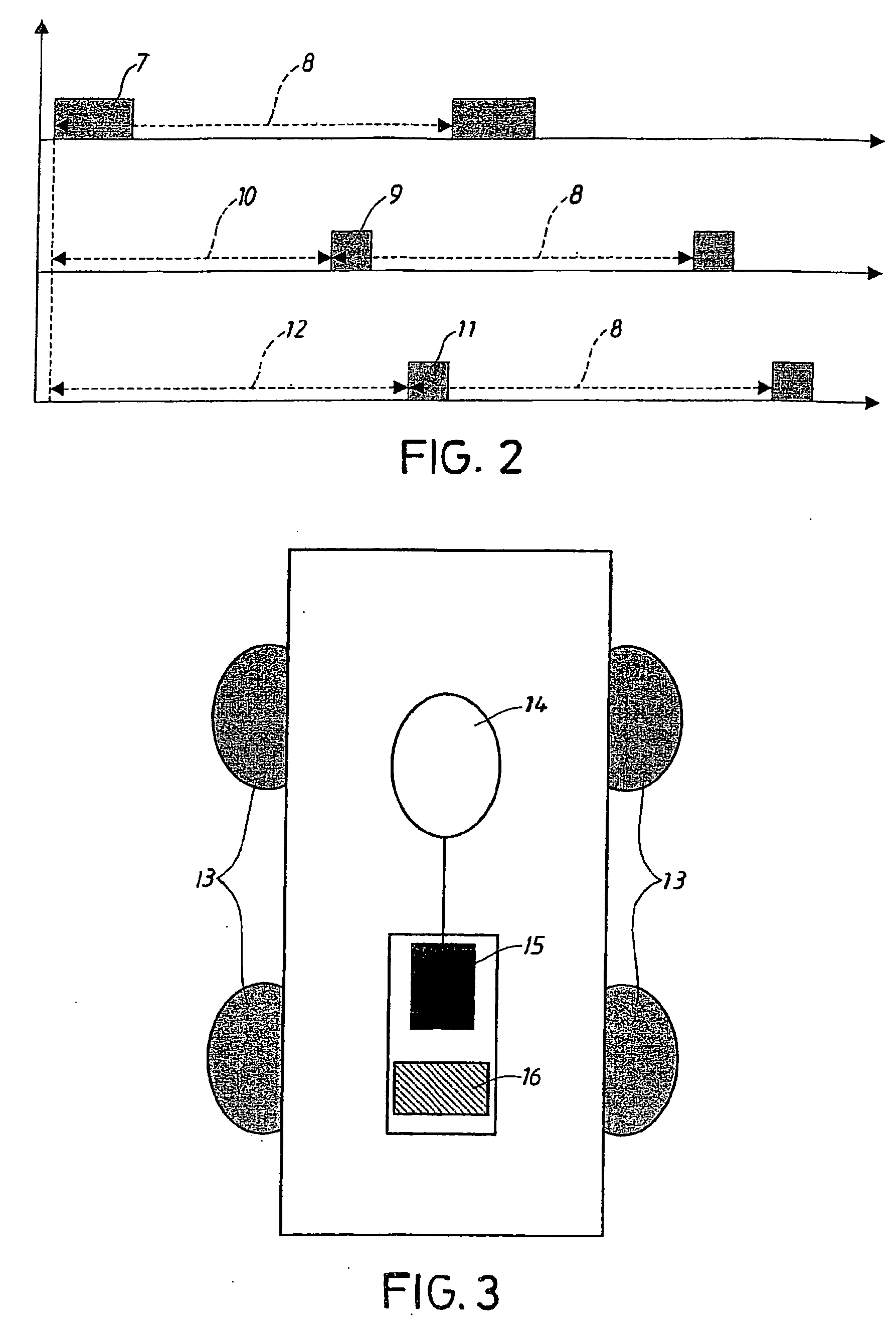
[0019] Examples of embodiments of a control system in accordance with the invention are shown in the figures. The examples of the embodiments shall not be interpreted as a limitation of the invention but their only purpose is to concretely shed light on preferred embodiments of the control system according to the invention. This is to further clarify the thought behind the invention.

[0020] The intention of the invention relates to developing a system using a navigational control station to direct a robot towards a specific target. The station area of the navigational control station, constituting the range of the station, shall be so small that the robot normally cannot move within this area and if the area is vertically positioned, the robot will never move inside the area. Besides, the magnetic field generated by the station shall be so strong that it can be sensed by the robot within a navigational control area extending inside and outside the station area. The generated magneti...


PUM


Abstract

The present invention relates to an arrangement and electronic navigational control system for a self-propelling device (5), preferably a lawn-mowing robot. The system comprises at least one navigational control system (3) connected to at least one signal generator (1) and a sensing unit arranged at the self-propelling device (5). The sensing unit senses at least one, in the air medium propagating, time and space varying magnetic field, at least transmitted via the navigational control station (3) and in turn retransmits at least one signal processed by the unit to at least one driving source which contributes to the device's movements across the surface. The system comprises means by which the signal generator (1) sends a current through the navigational control station (3), the current generating the time and space varying magnetic field, whereby the sensing unit comprises means by which the device (5) is manoeuvred based on the properties of the sensed magnetic field.

Description

TECHNICAL FIELD [0001] The present invention relates to a procedure and an electronic navigational control system for a self-propelling device, preferably a lawn-mowing robot. The system comprises at least one navigational control station connected to at least one signal generator and a sensing unit arranged at the self-propelling device. The sensing unit senses at least one time and space varying magnetic field propagating in the air medium, at least transmitted via the navigational control station and in turn retransmits at least one signal processed by the sensing unit to at least one driving source that contributes to the movements of the device across a surface. The invention relates to an electronic navigational control system comprising means by which the signal generator sends a current through a navigational control station. The current generates a time and space variable magnetic field, whereby the sensing unit comprises means by which the robot is controlled based on the ...

Claims


Application Information

Patent Timeline
Patent Type & Authority Applications(United States)
IPC IPC(8): G05D1/03A01D34/00G01S19/48G05D1/02
CPCA01D34/008A01D2101/00G05D1/0225G05D1/0265B60L2260/32B60L3/12B60L15/2036B60L2200/40B60L2220/46G05D2201/0208Y02T10/72Y02P90/60Y02T10/64
Inventor PETERSSON, ULFBERGVALL, BENGT-ALLAN
Owner HUSQVARNA AB
Why Eureka
Try Eureka