Disposable fluid flow sensor

a fluid flow sensor and dispersed technology, applied in the direction of measurement devices, volume/mass flow measurement, instruments, etc., can solve the problems of difficult to configure such devices for both limited use and in an inexpensive and efficient manner

Active Publication Date: 2005-12-08
HONEYWELL INT INC
View PDF19 Cites 11 Cited by
  • Summary
  • Abstract
  • Description
  • Claims
  • Application Information

AI Technical Summary

Benefits of technology

[0006] The following summary of the invention is provided to facilitate an understanding of some of the innovative features unique to the present invention and is not intende...

Problems solved by technology

One of the problems with conventional flow sensor packages is the difficulty in c...

Method used


Image

  • Disposable fluid flow sensor
  • Disposable fluid flow sensor
  • Disposable fluid flow sensor

Examples


Embodiment Construction

[0020] The particular values and configurations discussed in these non-limiting examples can be varied and are cited merely to illustrate at least one embodiment of the present invention and are not intended to limit the scope of the invention.

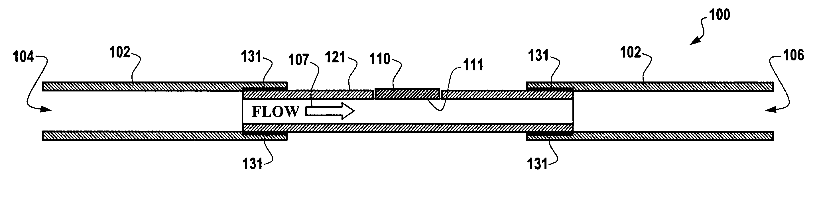
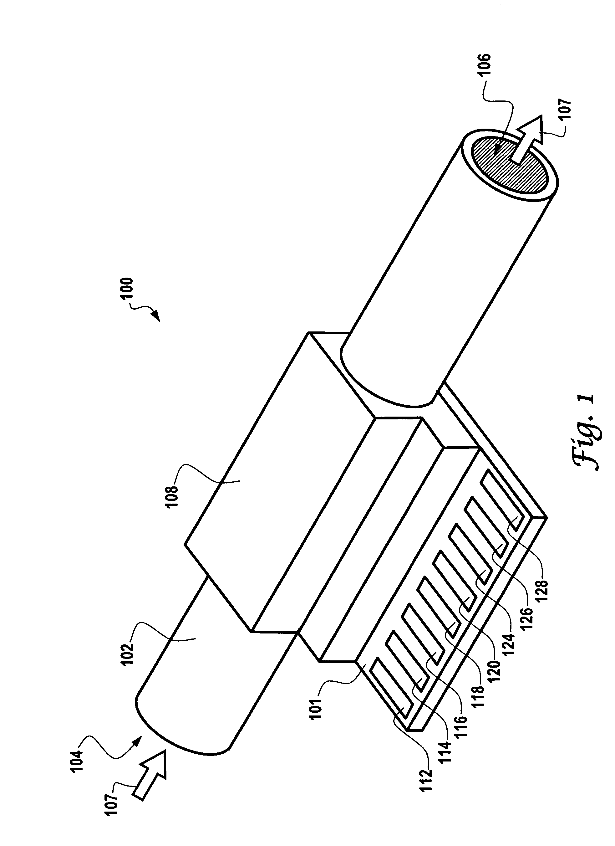
[0021]FIG. 1 illustrates a perspective view of a disposable fluid flow sensor 100, which can be implemented in accordance with a preferred embodiment of the present invention. Fluid flow sensor 100 generally includes a flow channel tube 102 which includes an entry portion 104 and an exit portion 106. Fluid flow into entry portion 104 and our of exit portion 106 is generally indicated by arrow 107. In the configuration depicted in FIG. 1, a flow channel assembly generally 108 surrounds flow channel tube 102 and can be connected to a substrate 101 upon which a plurality of electronic components 112, 114, 116, 118, 120, 124, 126 and 128 can be formed and located. Note that the electronic components 112, 114, 116, 118, 120, 124, 126 and 128 can b...


PUM


Abstract

A disposable fluid flow sensor is disclosed herein, which generally includes a flow channel assembly comprising a flow channel tube in association with a disposable flow channel portion. A sensor die is located approximate to a thin interface or membrane formed from the disposable flow channel portion, such that the sensor die measures a flow of fluid flowing through the flow channel tube and the disposable flow channel portion of the flow channel assembly. Additionally, a substrate can be provided upon which the sensor die is formed and located. A seal can also be provided for sealing the disposable flow channel portion to the flow channel tube. Such a flow sensor can be implemented in the context of a “non-isolated” sensor die approach in which the sensor die, substrate and flow tube are assembled together into a complete disposable assembly, in which a thin interface does not cover the sensor die. The flow sensor can also be implemented in the context of an “isolated” sensor die approach in which a thin membrane material or thin interface prevents the fluid from touching the surface of the sensor die. In such an “isolated” configuration, the sensor die is not actually part of the disposable flow tube assembly. The only disposable portion in this approach is the flow tube itself.

Description

CROSS-REFERENCE TO RELATED APPLICATION [0001] This patent application claims priority under 35 U.S.C. § 119(e) to provisional patent application Ser. No. 60 / 578,280 entitled “Disposable Fluid Flow Sensor”, which was filed on Jun. 8, 2004, the disclosure of which is incorporated herein by reference.TECHNICAL FIELD [0002] Embodiments are generally related to flow sensing devices and techniques. Embodiments are also related to disposable flow sensor packages. Embodiments are also related to sensor die and electronic processing components thereof. BACKGROUND OF THE INVENTION [0003] Many sensing applications require the use of liquid flow sensors. Flow sensors, for example, can be utilized for measure flow rates in a variety of commercial, industrial and medical applications. Various medical, process, and industrial applications, ranging from portable ventilators supplying anesthetizing agents to large-scale processing plants in a chemical plant require the use of flow sensors. In such a...

Claims


Application Information

Patent Timeline
IPC IPC(8): G01F1/00G01F1/68G01F1/684
CPCG01F1/6847G01F1/6845
Inventor REPKO, MARK A.ALDERMAN, RICHARD A.SIES, DUANE J.
Owner HONEYWELL INT INC
Why Eureka
Try Eureka