
Tension device for use with a self-retracting lifeline

a self-retracting and lifeline technology, applied in the direction of safety belts, sports equipment, cleaning equipment, etc., can solve the problem of ratcheting effect still occurring, and achieve the effect of reducing the slack in the lifelin

Active Publication Date: 2005-12-08
D B IND
View PDF17 Cites 27 Cited by
  • Summary
  • Abstract
  • Description
  • Claims
  • Application Information

AI Technical Summary

Benefits of technology

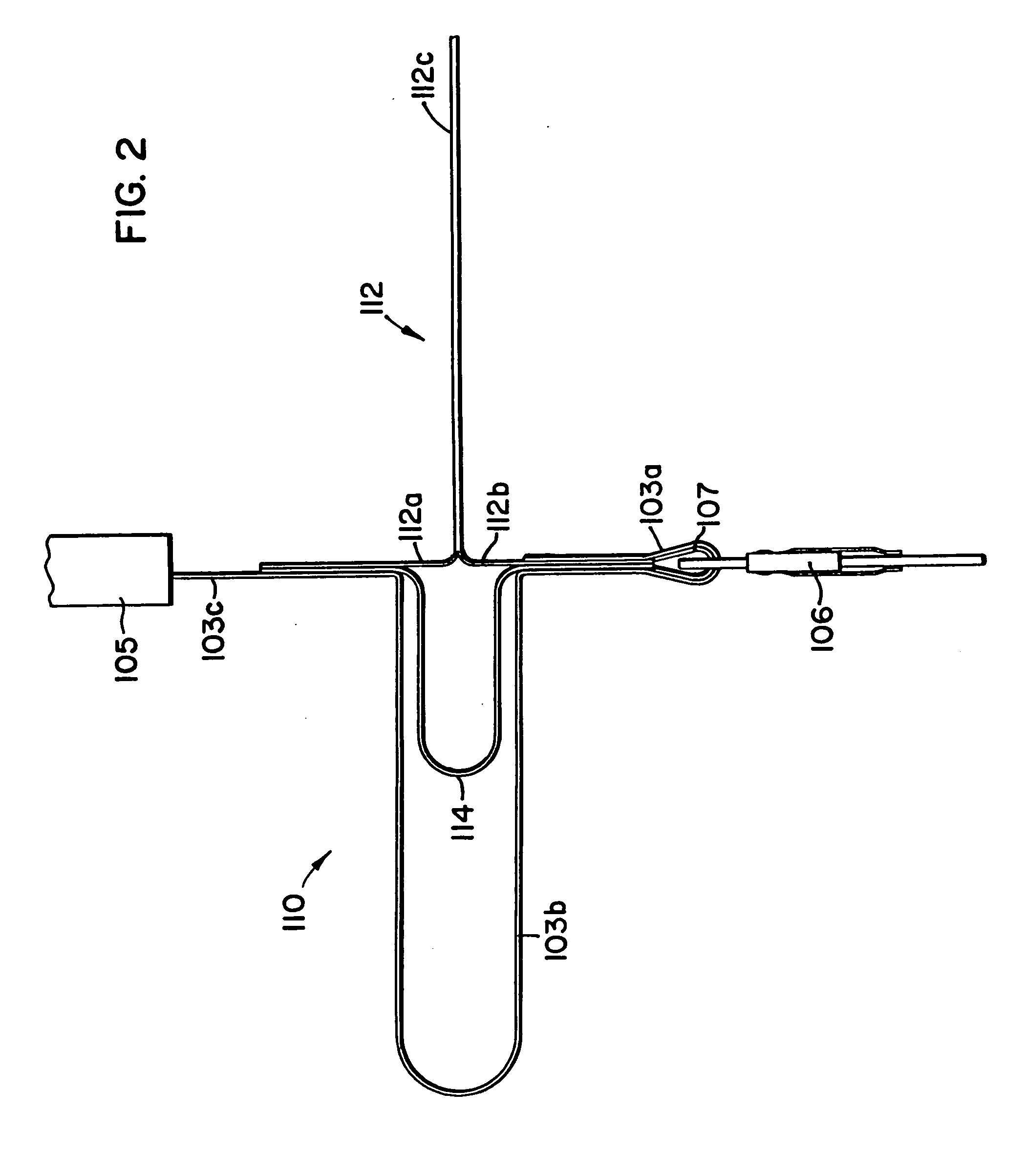
[0008] A preferred embodiment tension device for use with a self-retracting lifeline including a drum includes a lifeline and an elastic member. The lifeline has a retracting end, an intermediate portion, and a connecting end. The retracting end is operatively connected to the drum and the connecting end is releasably connectable to a user. The lifeline includes slack proximate the intermediate portion. The elastic member interconnects the retracting end and the connecting end. The elastic member provides tension on the lifeline and prevents the drum from retracting the lifeline when the connecting end of the lifeline rebounds in an upward direction during a fall.
[0010] A preferred embodiment tension device for use with a self-retracting lifeline including a drum includes a lifeline and means for providing tension on the lifeline. The lifeline has a retracting end, an intermediate portion, and a connecting end. The retracting end is operatively connected to the drum and the connecting end is releasably connectable to a user. The means for providing tension on the lifeline interconnects the retracting end and the connecting end and prevents the drum from retracting the lifeline when the connecting end of the lifeline rebounds in an upward direction during a fall.
[0011] A preferred embodiment tension device for use with a self-retracting lifeline including a drum includes a lifeline, an elastic member, and a shock absorber. The lifeline has a retracting end, an intermediate portion, and a connecting end. The retracting end is operatively connected to the drum and the connecting end is releasably connectable to a user. The lifeline includes slack proximate the intermediate portion. The elastic member interconnects the retracting end and the connecting end. The shock absorber interconnects the retracting end and the connecting end proximate the intermediate portion and the elastic member. The shock absorber includes a first portion and a second portion. The first portion and the second portion separate to absorb shock as the slack in the lifeline is reduced during a fall, and the elastic member provides tension on the lifeline and prevents the drum from retracting the lifeline when the connecting end of the lifeline rebounds in an upward direction during a fall.

Problems solved by technology

Although the shock absorber reduces the force of the fall, the ratcheting affect may still occur during a fall.

Method used


Image

  • Tension device for use with a self-retracting lifeline
  • Tension device for use with a self-retracting lifeline
  • Tension device for use with a self-retracting lifeline

Examples


Embodiment Construction

[0017] A preferred embodiment tension device for use with a self-retracting lifeline constructed according to the principles of the present invention is designated by the numerals 110 and 110′ in the drawings.

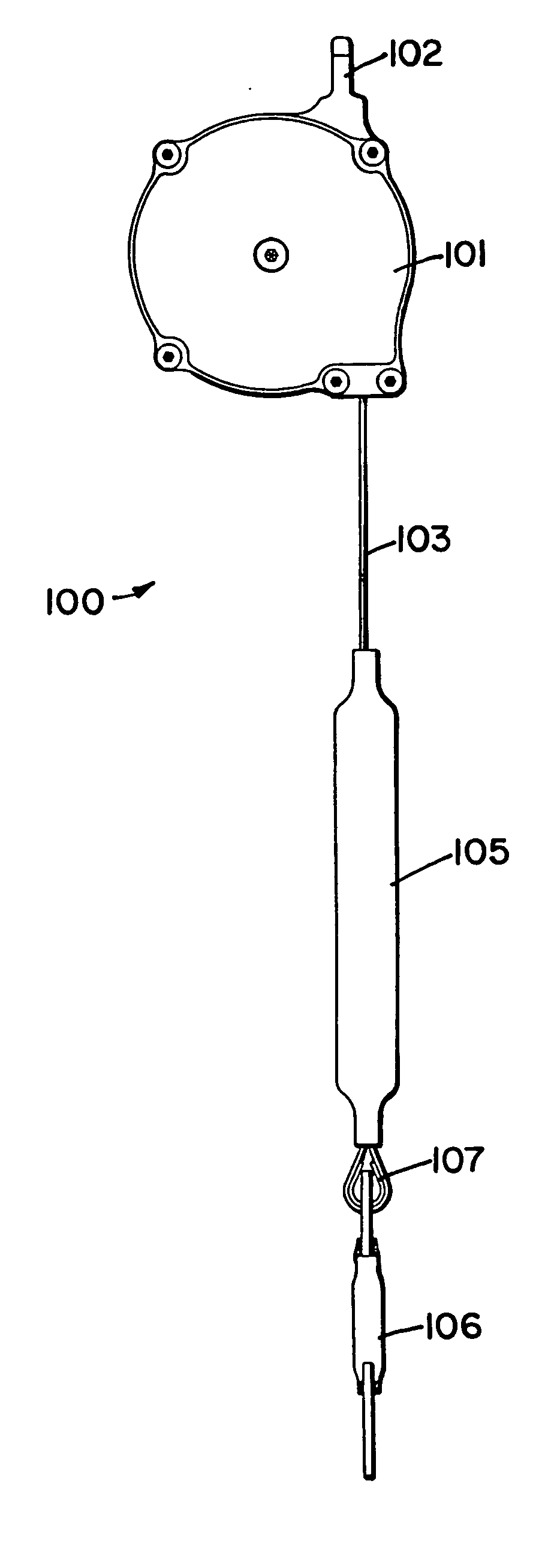
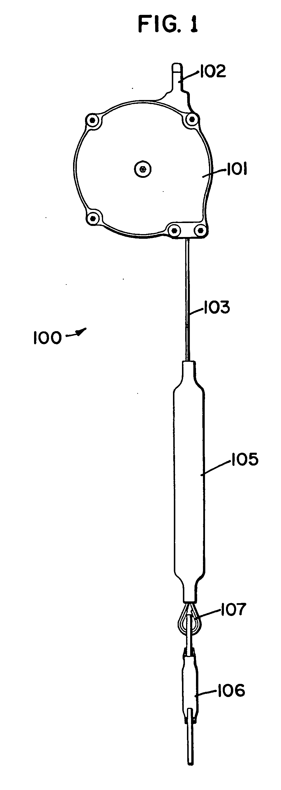
[0018] As shown in FIG. 1, a self-retracting lifeline 100 includes a housing 101 having a connecting member 102 through which a connector (not shown) such as a hook may be used to connect the housing 101 to a support structure. The housing 101 is configured and arranged to contain a drum (not shown) around which a lifeline 103 is wound. The drum is spring biased to pay out the lifeline 103 as tension pulling the lifeline 103 is applied and to retract any of the lifeline 103 that has been unwound from the drum as the tension on the lifeline 103 is reduced or released. The housing 101 also includes a brake assembly (not shown) for stopping rotation of the drum when the lifeline 103 suddenly unwinds from the drum at a rate greater than a predetermined maximum angular velocity. Pr...


PUM


Abstract

A tension device for use with a self-retracting lifeline having a drum includes a lifeline and an elastic member. The lifeline has a retracting end, an intermediate portion, and a connecting end. The retracting end is operatively connected to the drum, and the connecting end is releasably connectable to a user. The elastic member interconnects the retracting end and the connecting end. The elastic member provides tension on the lifeline and prevents the drum from retracting the lifeline when the connecting end of the lifeline rebounds in an upward direction during a fall.

Description

BACKGROUND OF THE INVENTION [0001] 1. Field of the Invention [0002] The present invention relates to a tension device for use with a self-retracting lifeline. [0003] 2. Description of the Prior Art [0004] Self-retracting lifelines are well known in the art of fall protection safety equipment for use by users performing tasks during which there is a risk a fall may occur. Self-retracting lifelines generally include a housing containing a drum around which a lifeline made of cable, rope, or webbing is wound. The drum is spring biased to pay out the lifeline as tension pulling the lifeline is applied and to retract any of the lifeline that has been unwound from the drum as the tension on the lifeline is reduced or released. In other words, the lifeline is paid out as the user moves away from the housing and the lifeline is retracted as the user moves toward the housing. The housing also includes a brake assembly for stopping rotation of the drum when the lifeline suddenly unwinds from ...

Claims


Application Information

Patent Timeline
Patent Type & Authority Applications(United States)
IPC IPC(8): A62B1/16A62B35/04
CPCA62B35/0093
Inventor CASEBOLT, SCOTT C.
Owner D B IND
Learn More