Modular fuel injector with a damper member and method of reducing noise

a technology of modular fuel injector and damper member, which is applied in the direction of noise reduction fuel injection, fuel injection apparatus, charge feed system, etc., can solve problems such as difficult installation, and achieve the effect of reducing the amplitude of vibration

Inactive Publication Date: 2005-12-08
SIEMENS VDO AUTOMOTIVE CORP
View PDF13 Cites 14 Cited by
  • Summary
  • Abstract
  • Description
  • Claims
  • Application Information

AI Technical Summary

Benefits of technology

[0006] In yet another aspect, the present invention provides for a method of maintaining operational noise of a fuel injector at a predetermined noise level. The fuel injector has a body extending along a longitudinal axis and a valve group subassembly. The valve group subassembly includes an inlet tube having a portion disposed within the body. The method can be achieved by reducing the amplitude of vibration of the inlet tube being transmitted across an annular gap formed between an outer circumferential portion of the inlet tube and the body during operation of the fuel injector with a generally conical member having an outer surface contiguous to a surface of the inlet tube to define at least one circumferential band about the longitudinal axis in the inlet tube; and quantifying the reduction of the amplitude of vibration in the form of a standardized measured noise level output.

Problems solved by technology

In one example, annular dampening elements also have been included as part of the fuel injector nozzle body, but at the fuel-metering section of the armature such that it is believed to be difficult to install, particularly post-manufacturing.

Method used


Image

  • Modular fuel injector with a damper member and method of reducing noise
  • Modular fuel injector with a damper member and method of reducing noise
  • Modular fuel injector with a damper member and method of reducing noise

Examples


Embodiment Construction

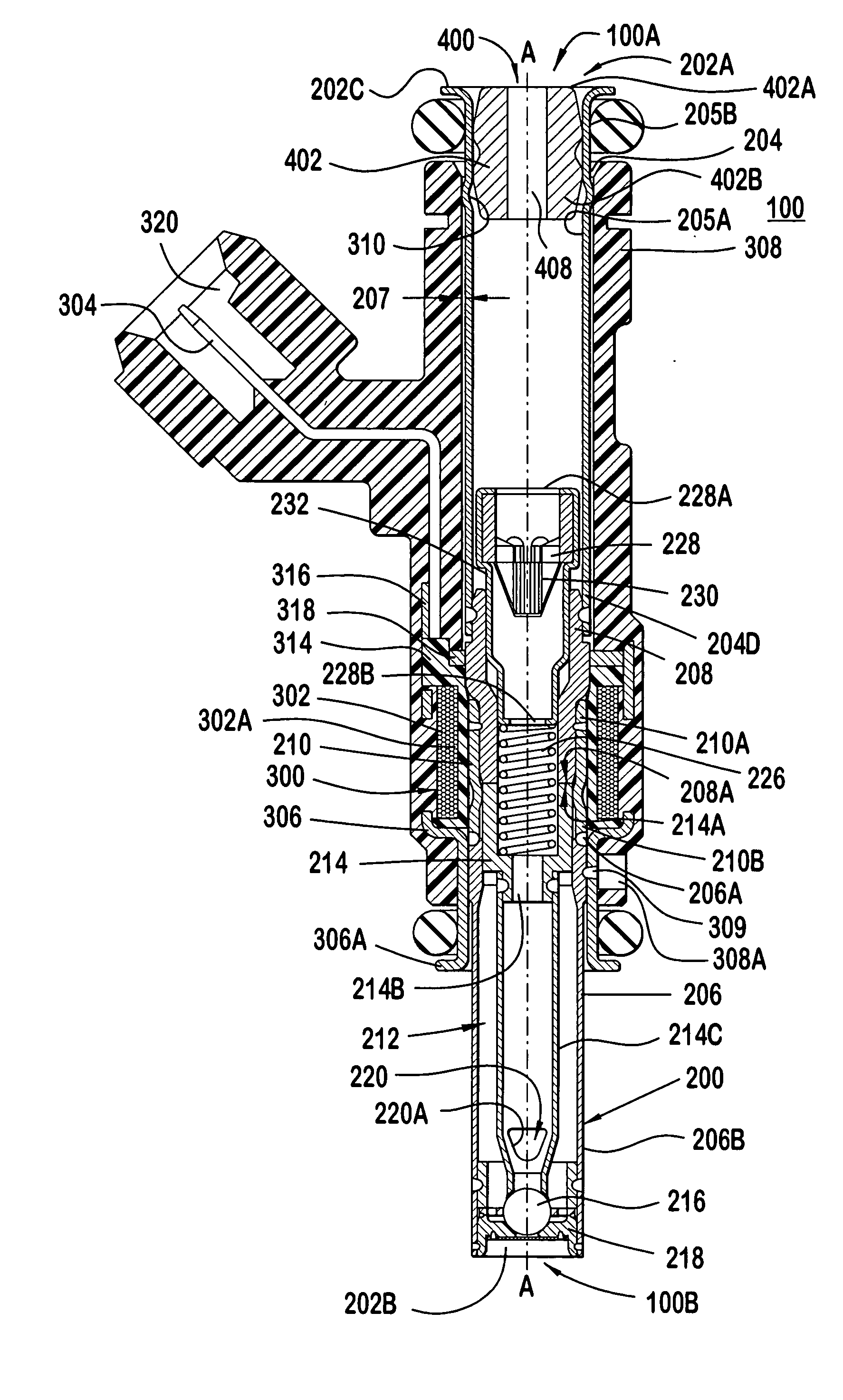
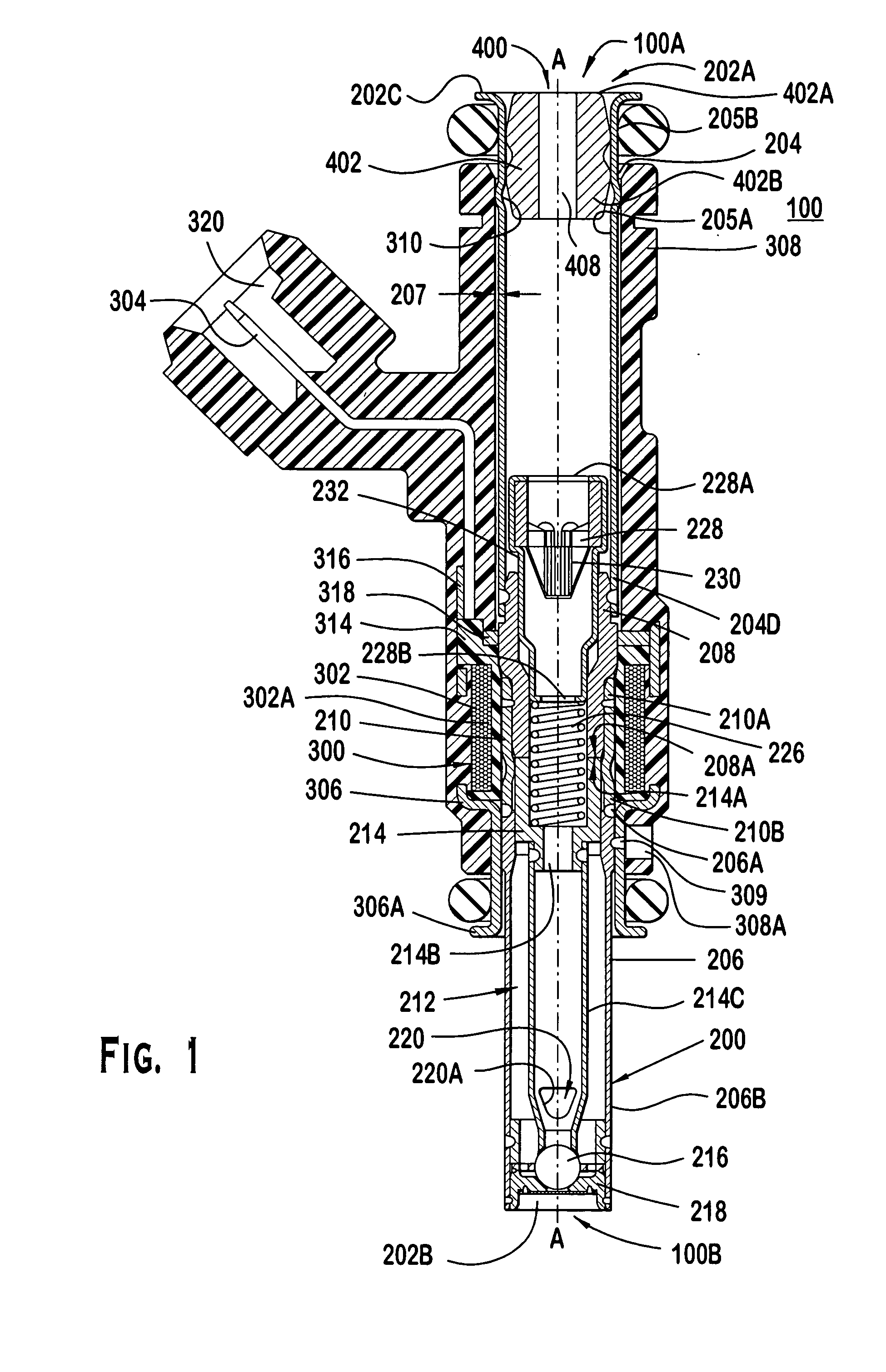
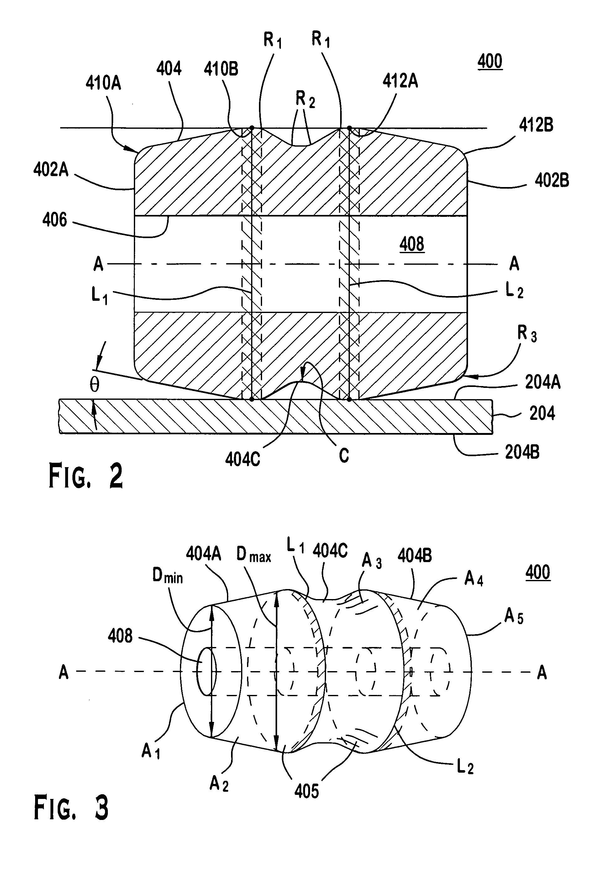
[0011]FIGS. 1-3 illustrate preferred embodiments. Referring to FIG. 1, a solenoid actuated fuel injector 100 dispenses a quantity of fuel to be combusted in an internal combustion engine (not shown). The fuel injector 100 extends along a longitudinal axis A-A between a first injector end 100A and a second injector end 100B, and includes a valve group subassembly 200, a power group subassembly 300 and a damper member 400. The valve group subassembly 200 performs fluid-handling functions, e.g., defining a fuel flow path and prohibiting fuel flow through the injector 100 when a closure member 216 is not actuated. The power group subassembly 300 performs electrical functions, e.g., converting electrical signals to a driving force for permitting fuel flow through the injector 100. The damper member 400 performs a noise reduction function, e.g., attenuating vibrations being transmitted through the fuel injector and therefore reduces acoustic noise emanating from the fuel injector.

[0012] ...


PUM


Abstract

A fuel injector includes a body, filter, and damper member. The body extends along a longitudinal axis between an inlet end and an outlet end and has a wall defining a flow passage extending therebetween. The filter is disposed in the flow passage proximate the inlet end. The damper member is secured to the flow passage between the inlet end and the filter. The damper member has outer and inner surfaces surrounding the longitudinal axis, the outer surface being contiguous to the wall of the flow passage to define at least one circumferential band about the longitudinal axis in the flow passage. The inner surface defines an aperture that extends through the damper member to permit fluid communication between the inlet end and the filter. A damper member is also shown and described. A method of reducing sound in the valve group subassembly is also disclosed.

Description

BACKGROUND OF THE INVENTION [0001] It is believed that some fuel injectors include features that reduce undesirable noise associated with operation of the fuel injector. For example, it has been known to locate a silencing chamber around the outlet end of the fuel injector. But this is believed to address noise caused by the expansion of gaseous fuel, not noise propagated by the actuator. [0002] It is also known to provide a noise insulator formed in or around the fuel injector to prevent transmission of noise from the fuel injector. In one example, annular dampening elements also have been included as part of the fuel injector nozzle body, but at the fuel-metering section of the armature such that it is believed to be difficult to install, particularly post-manufacturing. [0003] Another known example provides for a sound-dampening element formed unitarily as part of a fuel filter. The sound-dampening element, however, is believed to absorb noise propagating between the fuel injecto...

Claims


Application Information

Patent Timeline
Patent Type & Authority Applications(United States)
IPC IPC(8): F02M51/06F02M55/00F02M55/02F02M55/04F02M61/16F02M63/00
CPCF02M51/0682F02M55/00F02M61/16F02M61/165F02M2200/09F02M2200/27F02M2200/315F02M2200/505F02M2200/8015F02M2200/8053F02M2200/8084F02M2200/26F02M2200/306
Inventor CHO, YONG D.DALLMEYER, MICHAEL P.
Owner SIEMENS VDO AUTOMOTIVE CORP
Why Eureka
Try Eureka