Gasket assembly and method

a gasket and assembly technology, applied in the direction of engine sealing, engine sealing arrangement, machine/engine, etc., can solve the problems of assembly affecting the performance of the gasket, assembly can react with and degrade the plastic material used to form the gasket base, and is typically only used regularly on expensive race cars and perhaps other expensive vehicles

Inactive Publication Date: 2005-12-08
GRUNFELD ARON A
View PDF33 Cites 41 Cited by
  • Summary
  • Abstract
  • Description
  • Claims
  • Application Information

AI Technical Summary

Benefits of technology

[0012] According to another aspect of the invention, the gasket assembly may be used with a first engine component having a first passageway and a second engine component having a second passageway. The gasket assembly has a plastic base adapted to be disposed between the first engine component and the second engine component and defining an opening adapted to align with the first and second passageways when the base is disposed between the first and second engine components. The gasket assembly further has a protector in communication with the opening of the base and adapted to protect the base from a fluid flowing through the first passageway and the second passageway. In one preferred embodiment, the protector is in the form of a metal insert wherein the metal insert completely defines the opening for the fluid to pass therethrough.

Problems solved by technology

However, it has been discovered that certain types of coolants and / or other fluids currently being used in engine assemblies can react with and degrade the plastic material used to form the gasket bases.
Such a solution, however, is typically only used regularly on expensive race cars and perhaps other expensive vehicles due to the high cost involved in manufacturing such a gasket.
While gaskets according to the prior art provide a number of advantageous features, they nevertheless have certain limitations including those discussed above.

Method used


Image

  • Gasket assembly and method
  • Gasket assembly and method
  • Gasket assembly and method

Examples


Embodiment Construction

[0028] While this invention is susceptible of embodiment in many different forms, there is shown in the drawings and will herein be described in detail preferred embodiments of the invention with the understanding that the present disclosure is to be considered as an exemplification of the principles of the invention and is not intended to limit the broad aspect of the invention to the embodiments illustrated.

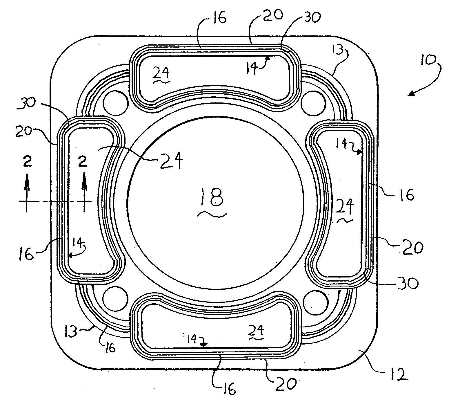
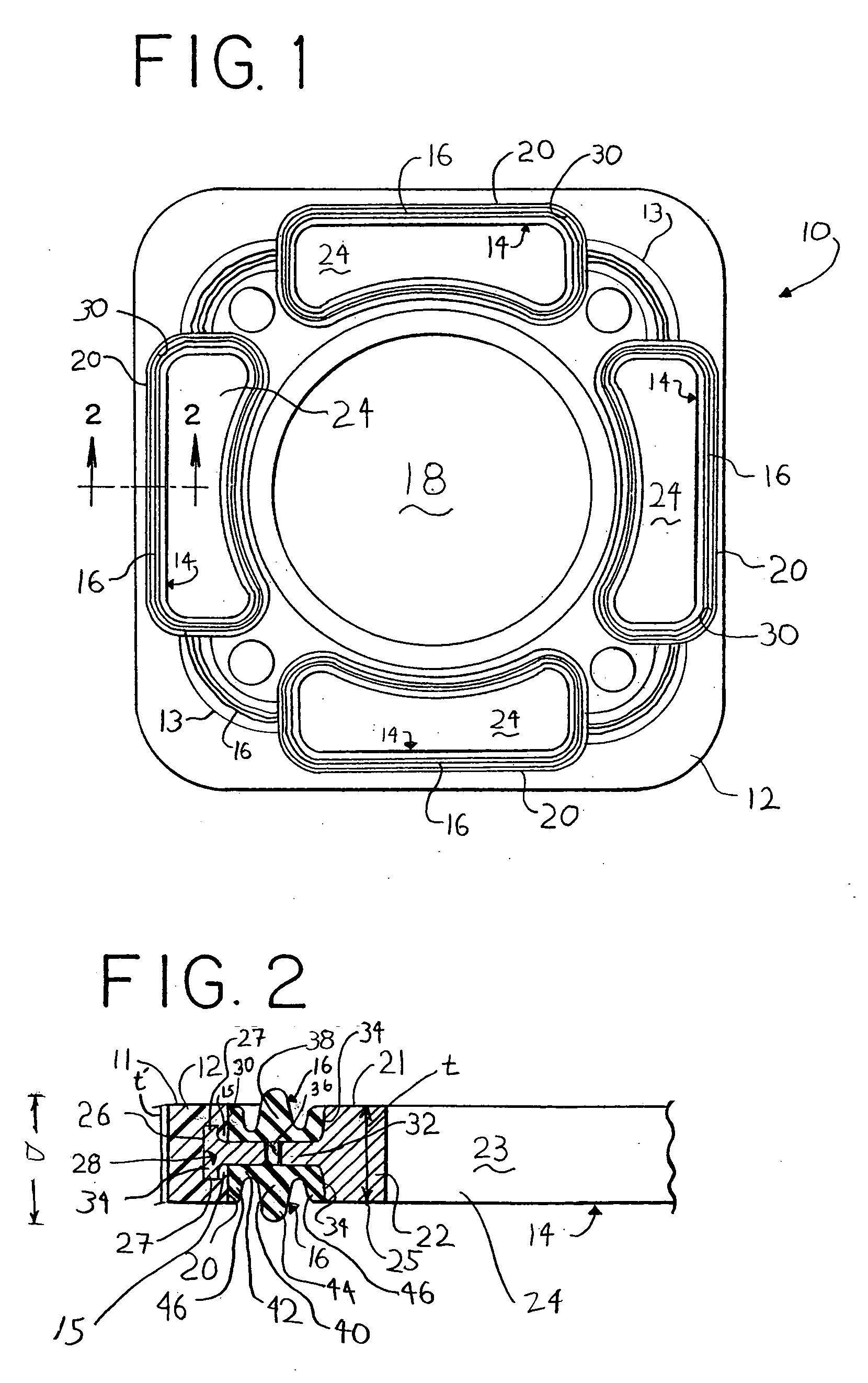
[0029]FIG. 1 shows a gasket or gasket assembly designated with the reference numeral 10. The gasket assembly 10 generally includes a base or carrier 12, an insert or protector 14 and a bead 16 of seal material.

[0030] As further shown in FIGS. 1 and 2, the base or carrier 12 is generally made from plastic and in a preferred embodiment, is injection-molded. This process will be described in greater detail below. The carrier 12 has a large central opening 18 or bore 18, and a plurality of smaller insert openings 20 surrounding the central bore 18. The carrier 12 also has a plura...


PUM


Abstract

A gasket assembly (10) for use with a first engine component having a first coolant passageway and a second engine component having a second coolant passageway is provided. The gasket assembly (10) comprises a plastic base (12) adapted to be disposed between the first engine component and the second engine component The plastic base (12) defines an opening (20) adapted to align with the first coolant passageway and the second coolant passageway when the base (12) is disposed between the first engine component and the second engine component. The gasket assembly (10) also includes a protector (14) associated with the coolant opening (20) of the base (12) and adapted to protect the base (12) from a coolant flowing through the first coolant passageway and the second passageway wherein the coolant is adapted to contact the protector (14) and not the base (12).

Description

TECHNICAL FIELD [0001] The present invention relates to gasket assemblies. More specifically, the present invention relates to a gasket assembly including a plastic carrier and a metal insert. BACKGROUND OF THE INVENTION [0002] Gaskets for providing a seal between mating parts of various devices are well known, as are gaskets for use in an automotive environment. One typical gasket comprises a plastic base having one or more openings. The opening is adapted to mate with, for instance, a coolant passageway of an engine assembly. Surrounding the opening and extending slightly from the gasket is usually a bead of an elastomeric material. When the gasket is sandwiched between an engine block and head, for example, the bead provides a fluid tight seal between the block, gasket and head. Such gaskets are also used in a wide variety of other applications. [0003] However, it has been discovered that certain types of coolants and / or other fluids currently being used in engine assemblies can ...

Claims


Application Information

Patent Timeline
Patent Type & Authority Applications(United States)
IPC IPC(8): F02F11/00F16J15/02F16J15/10F16J15/12
CPCF02F11/002F16J15/127F16J15/104
Inventor GRUNFELD, ARON A.
Owner GRUNFELD ARON A
Why Eureka
Try Eureka