
Repeater circuit with high performance repeater mode and normal repeater mode, wherein high performance repeater mode has fast reset capability

a high-performance repeater and repeater mode technology, applied in repeater/relay circuits, baseband system details, pulse techniques, etc., can solve the problems of insufficient rc constant maximum reduction, negative effects, propagation delay and distortion, etc., and achieve fast reset capability

Active Publication Date: 2005-12-08
INTELLECTUAL VENTURES HOLDING 81 LLC
View PDF16 Cites 15 Cited by
  • Summary
  • Abstract
  • Description
  • Claims
  • Application Information

AI Technical Summary

Benefits of technology

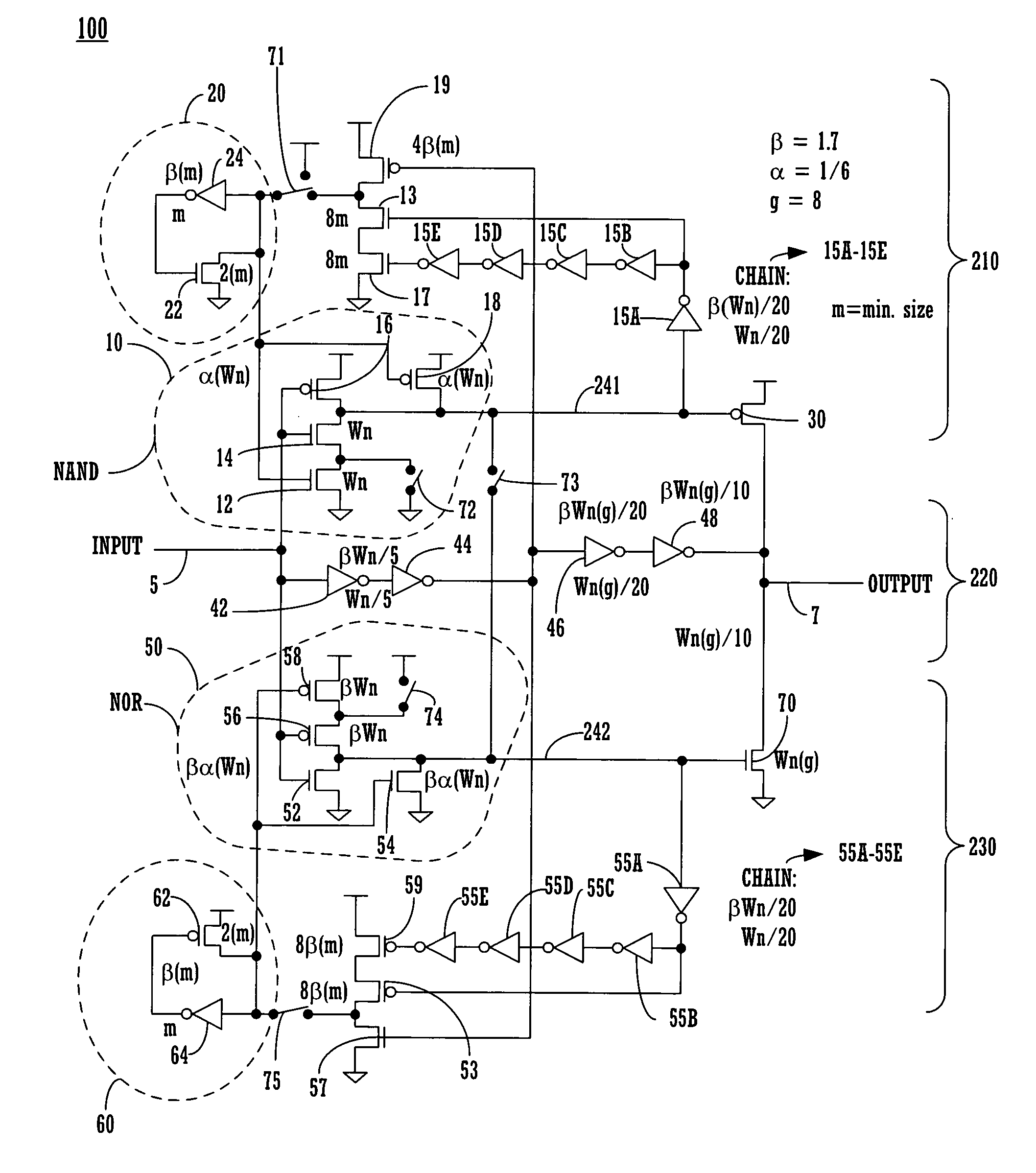
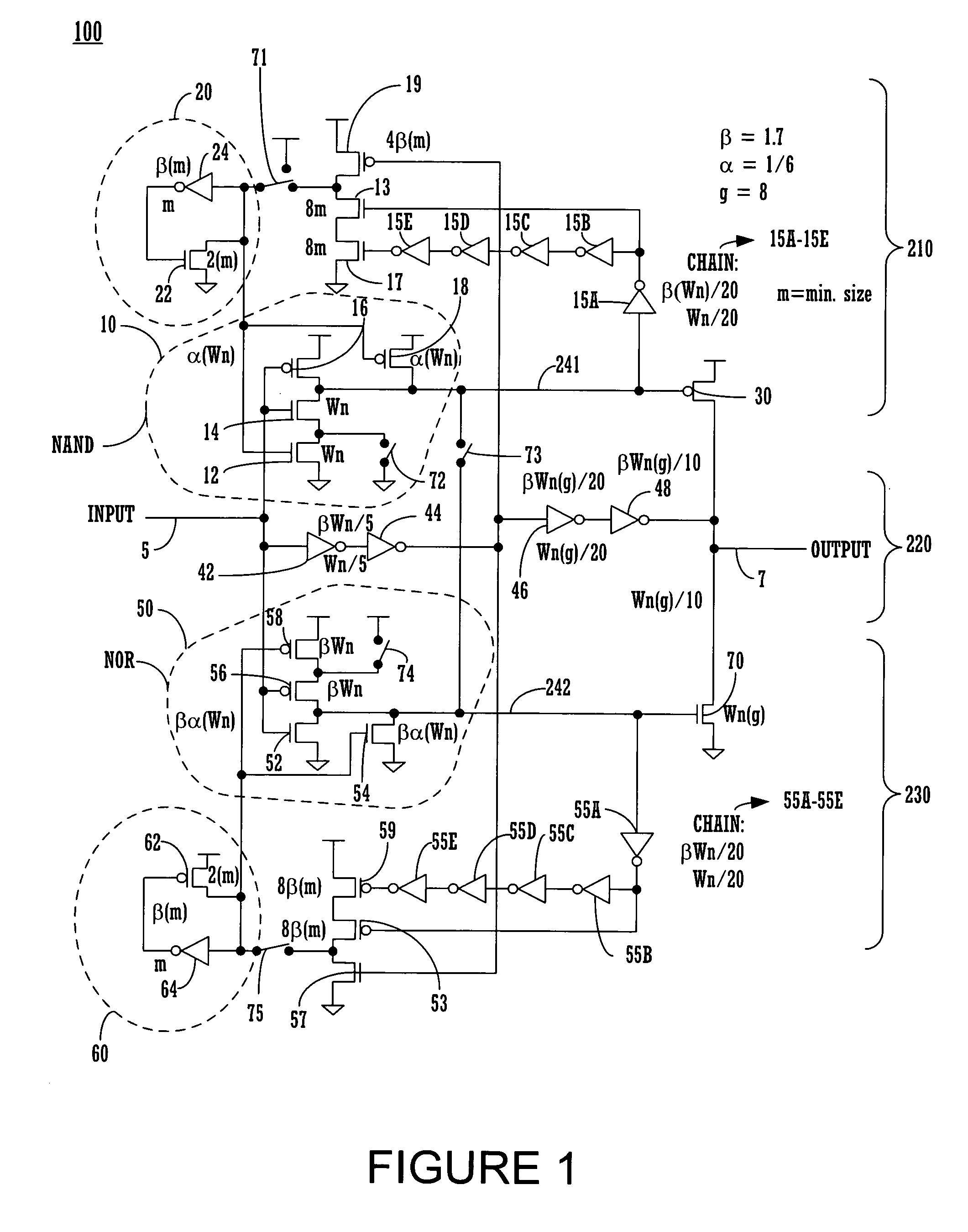
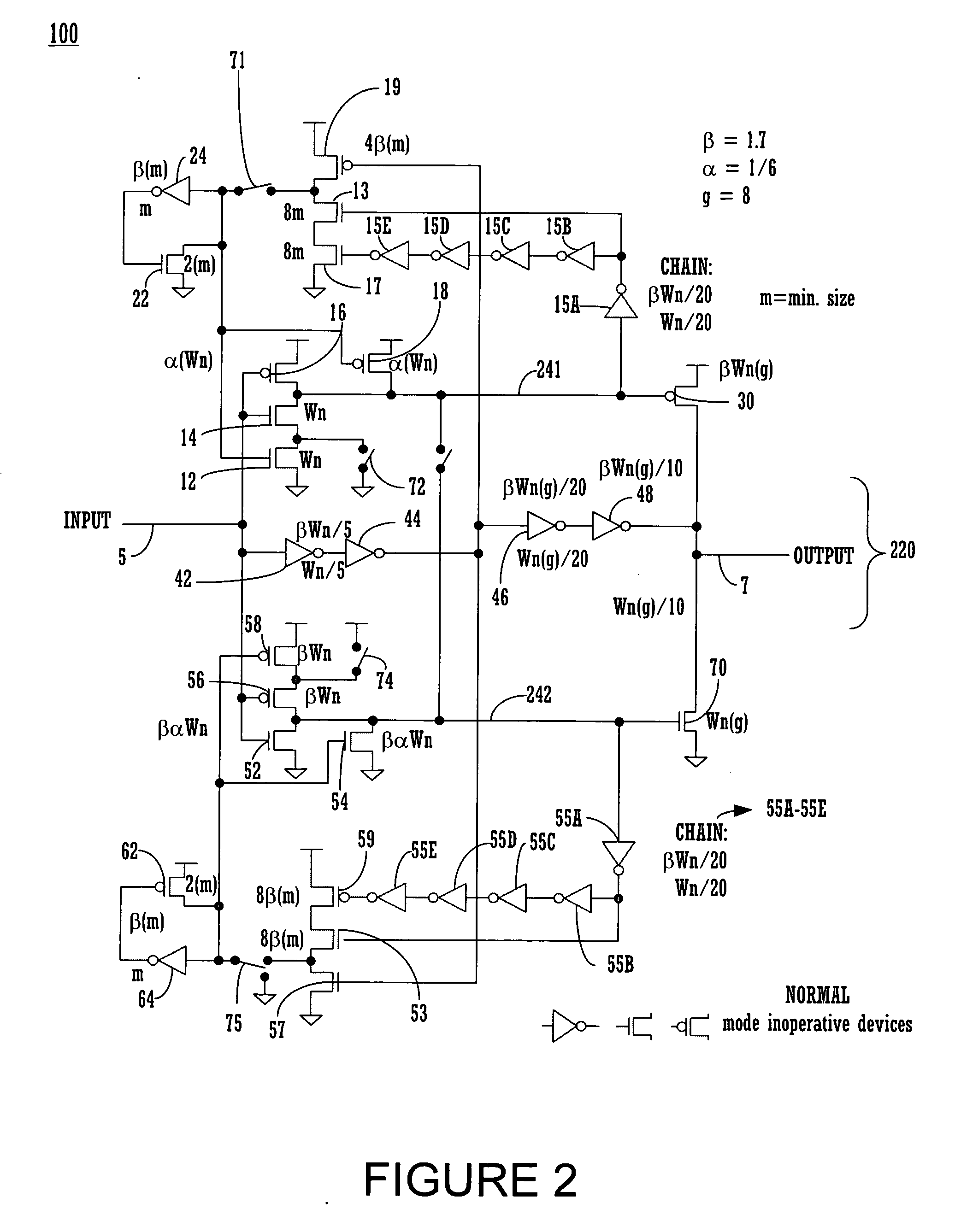
[0009] Repeater circuit with high performance repeater mode and normal repeater mode, wherein high performance repeater mode has fast reset capability, is provided and described. In one embodiment, switches are set to a first switch position to operate the repeater circuit in the high performance repeater mode. In another embodiment, switches are set to a second switch position to operate the repeater circuit in the normal repeater mode.

Problems solved by technology

Propagation delay and distortion are some of the negative effects experienced by the signals propagating along the long metal wires.
However, in some IC chip designs, the maximum reduction in the RC constant is not sufficient to meet the design specifications.

Method used


Image

  • Repeater circuit with high performance repeater mode and normal repeater mode, wherein high performance repeater mode has fast reset capability
  • Repeater circuit with high performance repeater mode and normal repeater mode, wherein high performance repeater mode has fast reset capability
  • Repeater circuit with high performance repeater mode and normal repeater mode, wherein high performance repeater mode has fast reset capability

Examples


Embodiment Construction

[0014] Reference will now be made in detail to embodiments of the present invention, examples of which are illustrated in the accompanying drawings. While the invention will be described in conjunction with these embodiments, it will be understood that they are not intended to limit the invention to these embodiments. On the contrary, the invention is intended to cover alternatives, modifications and equivalents, which may be included within the spirit and scope of the invention as defined by the appended claims. Furthermore, in the following detailed description of the present invention, numerous specific details are set forth in order to provide a thorough understanding of the present invention. However, it will be recognized by one of ordinary skill in the art that the present invention may be practiced without these specific details.

[0015] In general, repeater circuits can be classified as a high performance repeater circuit or a normal repeater circuit. Other classifications a...


PUM


Abstract

Repeater circuit with high performance repeater mode and normal repeater mode, wherein high performance repeater mode has fast reset capability, is provided and described. In one embodiment, switches are set to a first switch position to operate the repeater circuit in the high performance repeater mode. In another embodiment, switches are set to a second switch position to operate the repeater circuit in the normal repeater mode.

Description

CROSS REFERENCE TO RELATED APPLICATIONS [0001] This patent application is a Continuation-in-Part of U.S. patent application Ser. No. 10 / 864,271 by R. Masleid et al., filed on Jun. 8, 2004, entitled “Stacked Inverter Delay Chain,” with Attorney Docket No. TRAN-P326, assigned to the assignee of the present invention, and hereby incorporated by reference in its entirety. [0002] This patent application is related to U.S. patent application Ser. No. ______, filed on ______, entitled “Repeater Circuit with High Performance Repeater Mode and Normal Repeater Mode”, by R. Masleid et al., with Attorney Docket No. TRAN-P320, assigned to the same assignee of the present patent application, and hereby incorporated by reference in its entirety. [0003] This patent application is related to U.S. patent application Ser. No. ______ by R. Masleid et al., filed on ______, entitled “Circuits and Methods for Detecting and Assisting Wire Transitions,” with Attorney Docket No. TRAN-P331, assigned to the as...

Claims


Application Information

Patent Timeline
Patent Type & Authority Applications(United States)
IPC IPC(8): H03K19/017H03K19/0185H04L25/24
CPCH03K19/01721H04L25/242H03K19/018585
Inventor MASLEID, ROBERT PAULDHOLABHAI, VATSAL
Owner INTELLECTUAL VENTURES HOLDING 81 LLC
Learn More