Trigger signal generation system frame signal waveform observation system
- Summary
- Abstract
- Description
- Claims
- Application Information
AI Technical Summary
Benefits of technology
Problems solved by technology
Method used
Image
Examples
Embodiment Construction
[0076] An embodiment of the invention is explained below with reference to the drawings.
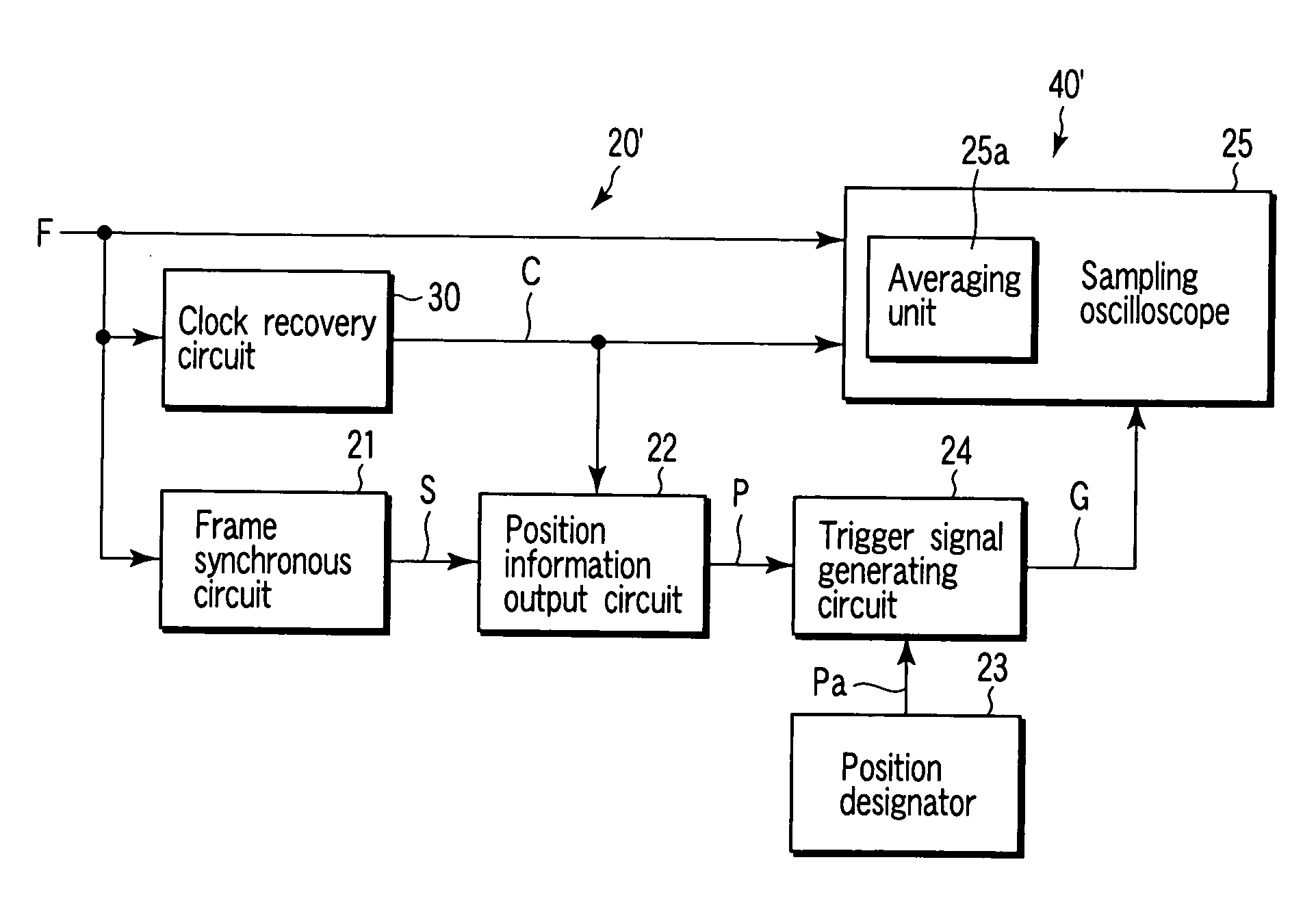
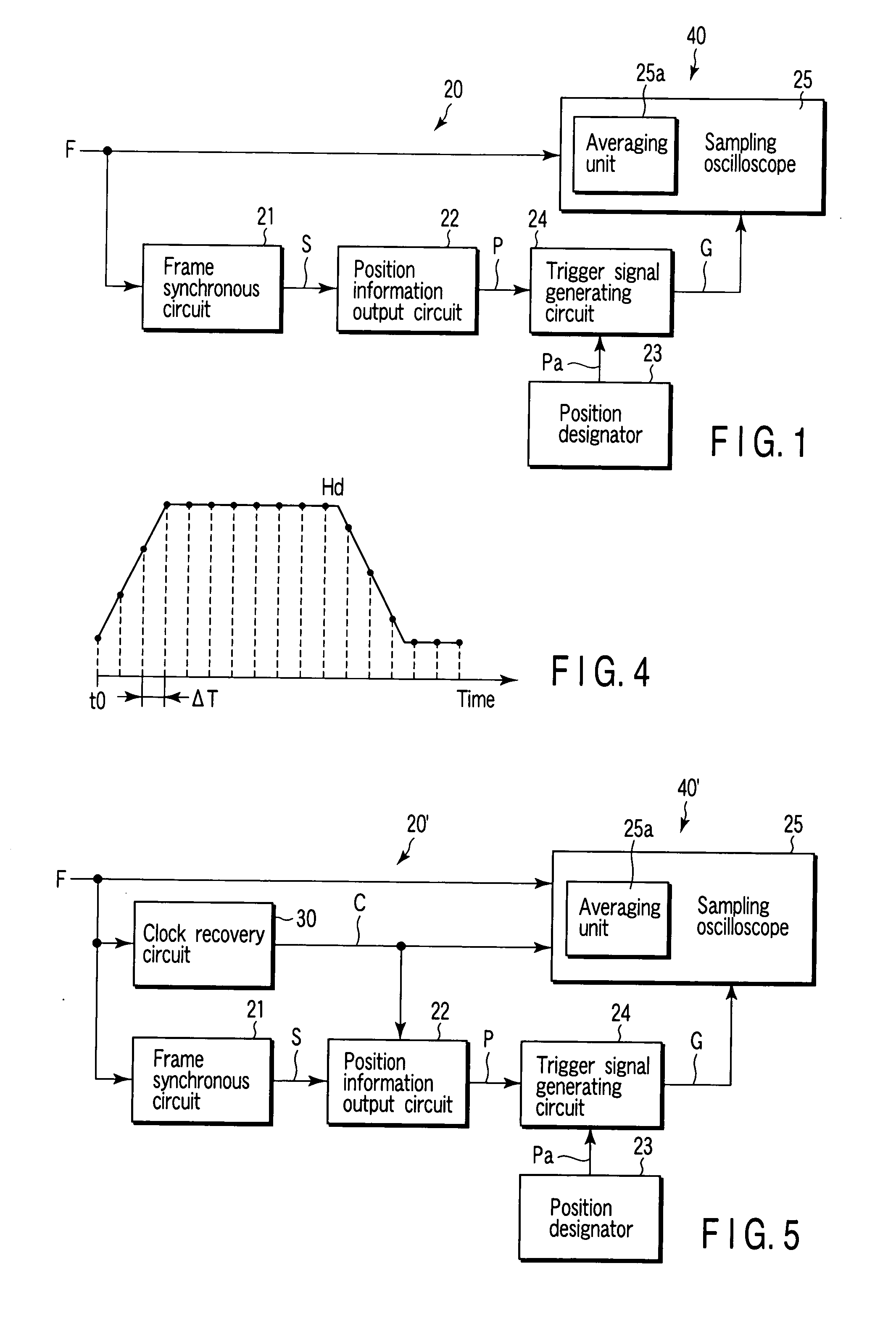
[0077]FIG. 1 is a block diagram for explaining the configuration according to an embodiment of the invention applicable to a trigger signal generating system including a trigger signal generating apparatus 20 and method and a frame signal waveform observation system including a frame signal waveform observation apparatus 40 and method using the trigger signal generating system.
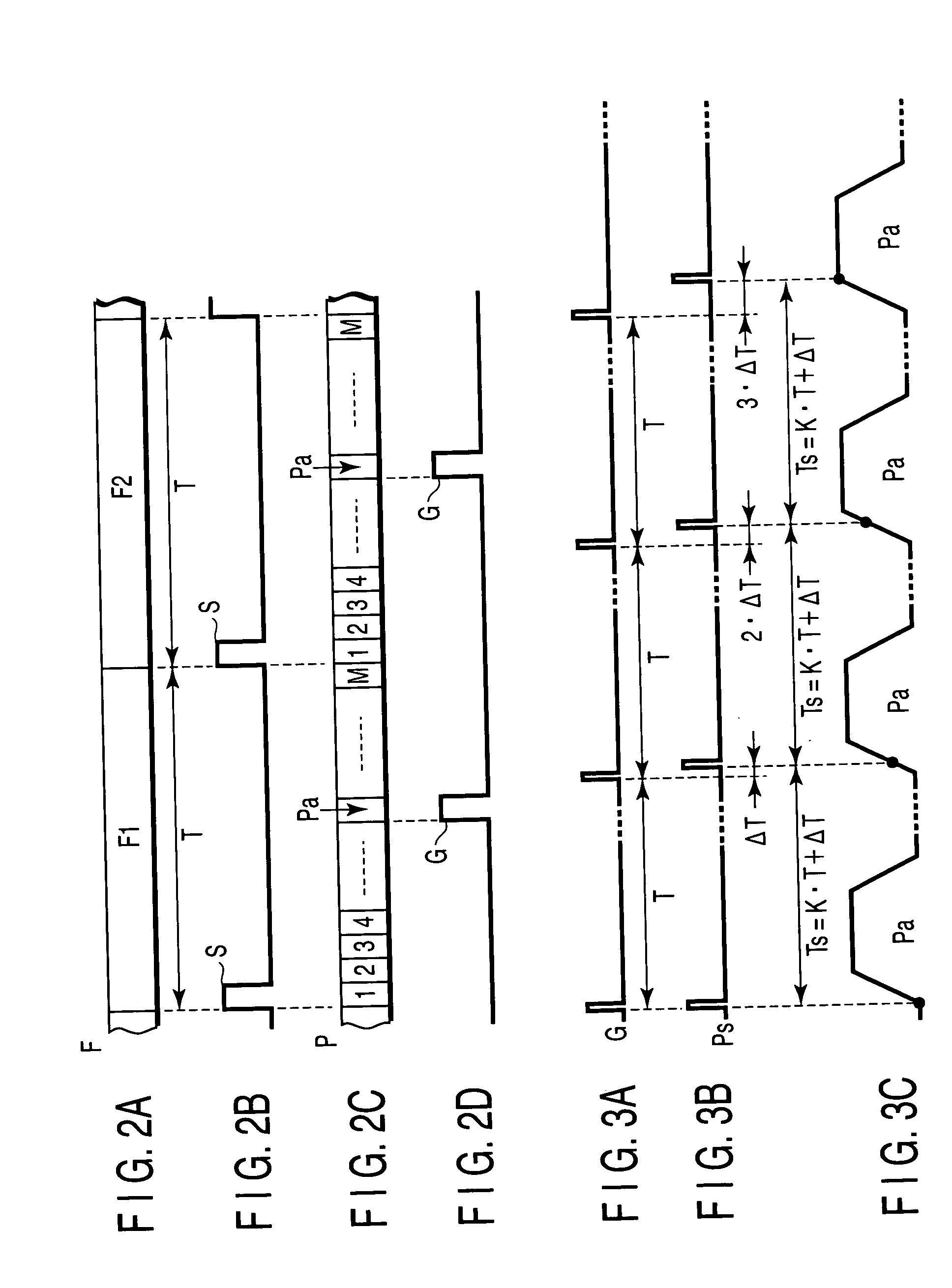
[0078] Specifically, the trigger signal generating apparatus 20 includes a frame synchronous circuit 21 which receives a frame signal of a predetermined bit rate and outputs a synchronous signal in synchronism with an input timing of leading data of the frame signal, a position information output circuit 22 which receives the synchronous signal output from the frame synchronous circuit 21 and outputs the position information indicating an input bit position of the frame signal, a position designator 23 which designates an...
PUM
 Abstract
Description
Claims
Application Information
 - R&D
- Intellectual Property
- Life Sciences
- Materials
- Tech Scout
- Unparalleled Data Quality
- Higher Quality Content
- 60% Fewer Hallucinations
Browse by: Latest US Patents, China's latest patents, Technical Efficacy Thesaurus, Application Domain, Technology Topic, Popular Technical Reports.
© 2025 PatSnap. All rights reserved.Legal|Privacy policy|Modern Slavery Act Transparency Statement|Sitemap|About US| Contact US: help@patsnap.com


