Electric reactor for electric power

A reactor, magnetron reactor technology, applied in reactive power compensation, reactive power adjustment/elimination/compensation and other directions, can solve the problem that the triggering situation cannot be accurately grasped in real time, the triggering state of the thyristor cannot be monitored in real time, and the accuracy of thyristor protection is inconvenient. and other problems to achieve the effect of preventing overvoltage breakdown, small ripple, and guaranteed triggering

Active Publication Date: 2015-01-28
SUZHOU IND PARK HESHUN ELECTRIC CO LTD
View PDF3 Cites 6 Cited by
  • Summary
  • Abstract
  • Description
  • Claims
  • Application Information

AI Technical Summary

Problems solved by technology

The traditional electromagnetic triggering method cannot monitor the triggering state of the thyristor in real time, and cannot accurately grasp the actual triggering situation in real time, which is not easy to achieve the accuracy of triggering and the protection of the thyristor.

Method used


Image

  • Electric reactor for electric power
  • Electric reactor for electric power
  • Electric reactor for electric power

Examples


Embodiment

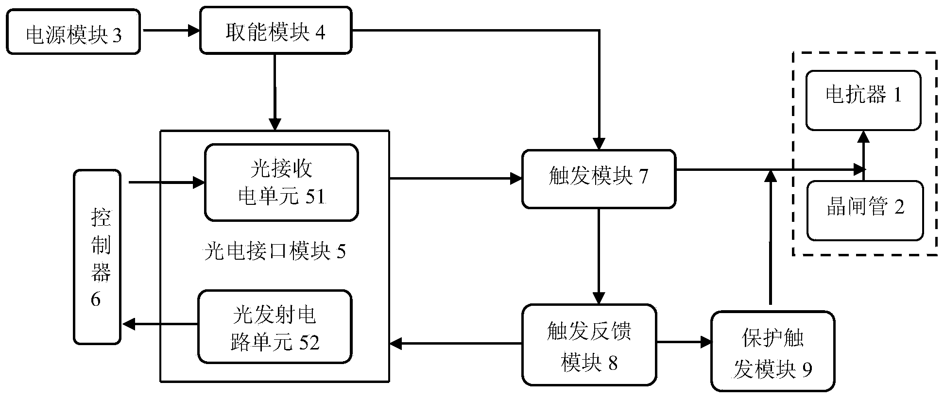
[0022] Embodiment: a power reactor, as attached Figure 1~4 As shown, the magnetron reactor includes a reactor 1 and a thyristor 2 for controlling the switching angle of the reactor 1;

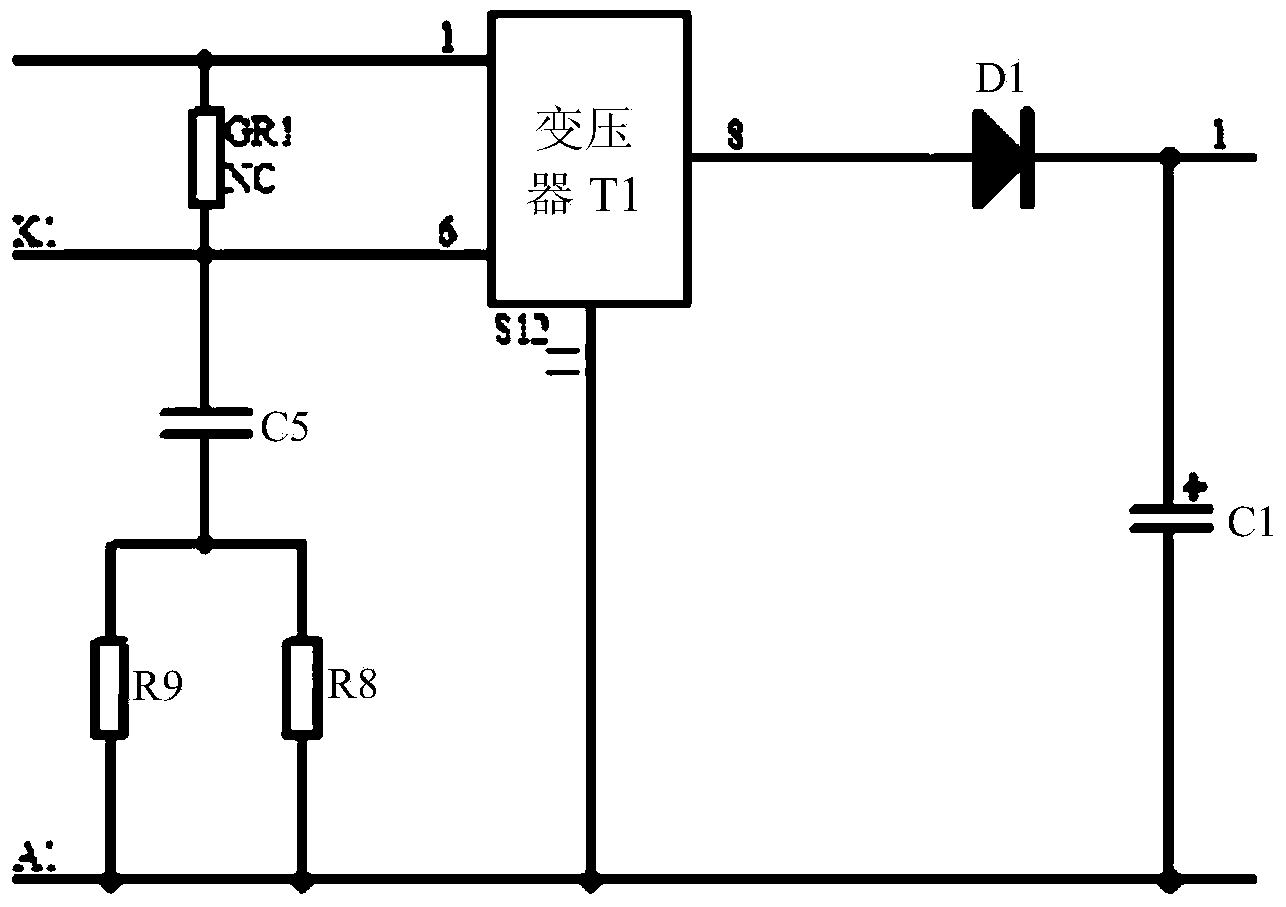
[0023] It also includes: a power module 3 connected to the mains, used to receive electric energy from the grid, which includes a transformer T1 and a first diode D1, the transformer T1 steps down the voltage from the mains and then passes through the first diode D1 Remove the positive half cycle to obtain DC voltage;

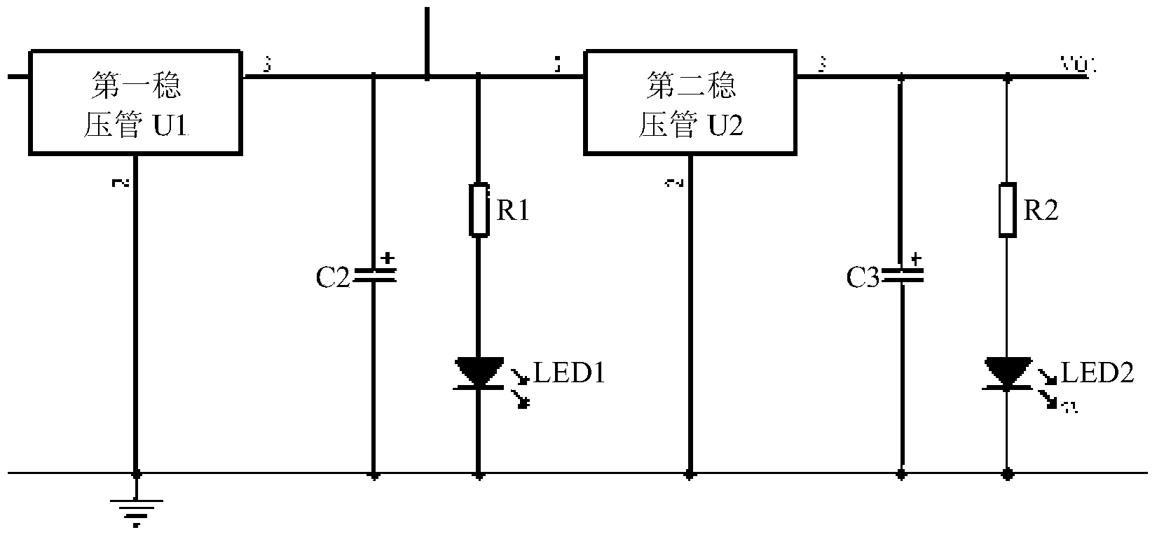
[0024] The energy harvesting module 4, the energy harvesting module 4 includes a first voltage regulator tube U1 and a second voltage regulator tube U2 connected in series, the first voltage regulator tube U1 converts the DC voltage from the power module 3 into a 12V voltage, The second voltage regulator tube U2 converts the 12V voltage from the first voltage regulator tube U1 into a 5V voltage. The first output end powered by the second diode D2, and the end of the second vo...


PUM


Abstract

The invention discloses an electric reactor for electric power. The electric reactor for electric power comprises a power module, an photoelectric interface module and a trigger module, wherein the power module is connected to the mains supply; the photoelectric interface module comprises an photoelectric receiving circuit unit and an photoelectric transmitting circuit unit, and the photoelectric receiving circuit unit is used for converting optical pulse signals from a controller into synchronous current signals. The trigger module is connected to the gate pole of a thyristor, amplifies and converts the synchronous current signals into current pulses driving the gate pole of the thyristor and comprises a pre-amplification circuit and a post-amplification circuit which are connected in series, wherein the pre-amplification circuit is composed of a second triode and a third triode, and the post-amplification circuit is formed by connecting a second diode and a third diode in series. A second capacitor is connected between the first output end and the ground in a bridge joint mode. A third capacitor is connected between the second output end and the ground in a bridge joint mode. A branch which is formed by connecting a first resistor and a first light-emitting diode in series is connected with the second capacitor in parallel. According to the electric reactor for electric power, real-time monitoring and protection can be carried out, and the electric reactor for electric power has the advantages of being accurate in triggering, high in stability and small in power consumption, and improving pulse quality and isolation performance.

Description

technical field [0001] The invention relates to a power reactor and belongs to the technical field of reactors. Background technique [0002] A reactor is also called an inductor. When a conductor is energized, it will generate a magnetic field in a certain space it occupies, so all electric conductors that can carry current have inductance in the general sense. However, the inductance of the energized long straight conductor is small, and the magnetic field generated is not strong, so the actual reactor is in the form of a solenoid wound with wires, which is called an air-core reactor; sometimes in order to make the solenoid have a larger inductance, The iron core is inserted into the solenoid, which is called iron core reactor. [0003] The introduction of reactive power compensation device in the power system for reactive power compensation, magnetron reactor (MCR) has been commonly used, it has played an important role in dynamic reactive power support and control of th...

Claims


Application Information

Patent Timeline
Patent Type & Authority Applications(China)
IPC IPC(8): H02J3/18
CPCY02E40/30H02J3/18
Inventor 李宁费远鹏刘辉
Owner SUZHOU IND PARK HESHUN ELECTRIC CO LTD
Why Eureka
Try Eureka