Quick response mechanism and method for a switching power system

a technology of switching power system and quick response mechanism, which is applied in the direction of electric variable regulation, process and machine control, instruments, etc., can solve the problems of output voltage vcore still significantly dropping, causing voltage spikes, and output voltage vcore still dropping below the specification, so as to accurately trigger a quick response, adjust the quick response width, the effect of accurately triggering a quick respons

Active Publication Date: 2012-04-17
RICHTEK TECH
View PDF1 Cites 6 Cited by
  • Summary
  • Abstract
  • Description
  • Claims
  • Application Information

AI Technical Summary

Benefits of technology

[0008]An object of the present invention is to provide a quick response mechanism for a switching power system, to accurately trigger a quick response and adjust the quick response width.
[0009]Another object of the present invention is to provide a quick response method for a switching power system, to accurately trigger a quick response and adjust the quick response width.
[0010]According to the present invention, a quick response mechanism for a switching power system has a detector and an adjustor connected to the detector. The detector is configured to directly monitor the drop of the output voltage of the switching power system, and trigger a quick response signal when the drop is greater than a threshold value. The adjustor is configured to adjust the width of the quick response signal. Since the drop of the output voltage is directly detected by the detector, the quick response mechanism will offer a faster reaction to a load transient. Moreover, the adjustor determines the quick response width to prevent the output voltage from undershoot or ringback.
[0011]According to the present invention, a quick response method for a switching power system comprises directly monitoring the drop of the output voltage of the switching power system to trigger a quick response signal and adjusting the width of the quick response signal to prevent the output voltage from undershoot or ringback.

Problems solved by technology

But if the load transient is relatively large, the output voltage Vcore still significantly drops.
On the contrary, a too fast quick response triggered before load transient occurs will induce a voltage spike.
Besides, if the quick response duration is too short, the output voltage Vcore may still drop below the specification because there is no enough charge in the output capacitor pool.
On the contrary, if the quick response duration is too long, the output voltage Vcore will rise high and causes a ringback.
It's difficult for a user to control the APA width because the low-pass filter 44 is built in the controller chip.
This is no good if the load transient slew rate is very high.

Method used


Image

  • Quick response mechanism and method for a switching power system
  • Quick response mechanism and method for a switching power system
  • Quick response mechanism and method for a switching power system

Examples


Embodiment Construction

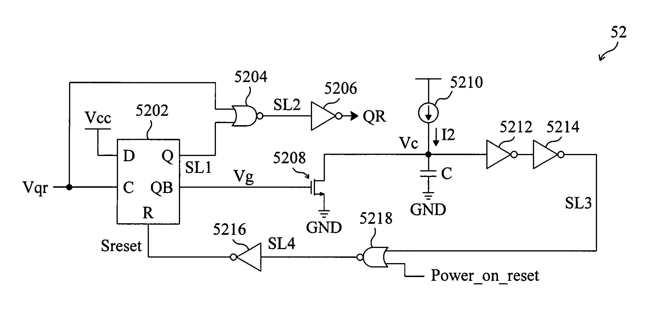
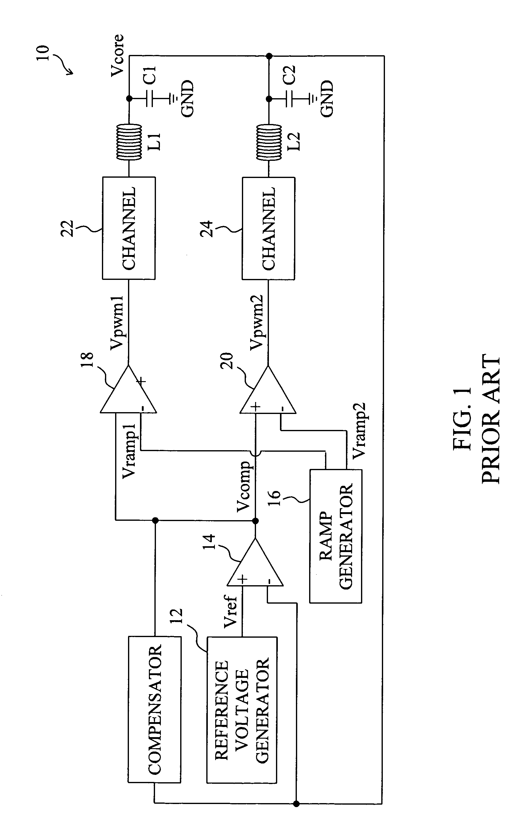
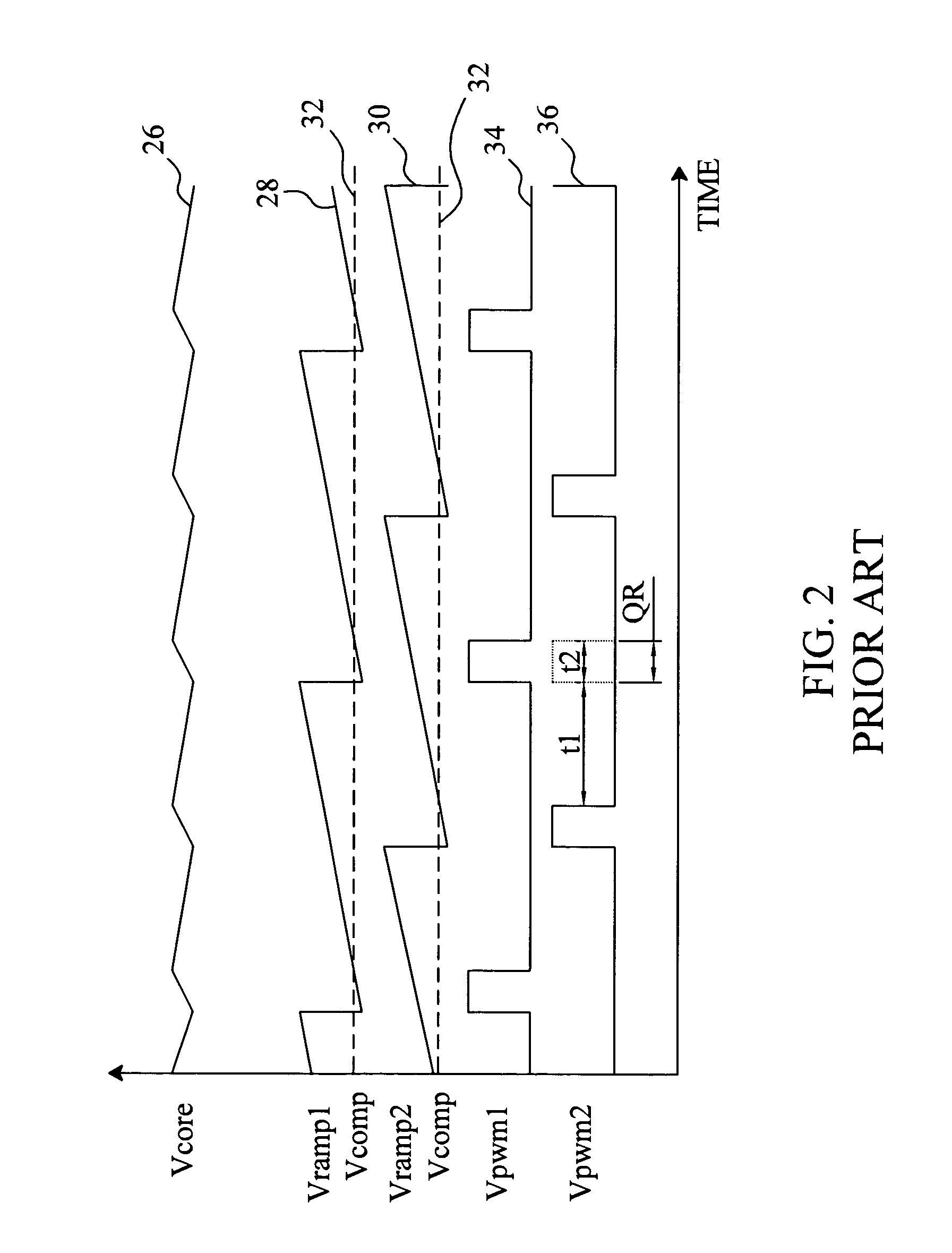
[0020]FIG. 4 is a perspective diagram of a quick response mechanism according to the present invention applied to a switching power system including a plurality of channels 54 for providing an output voltage Vcore. The quick response mechanism includes a detector 50 directly monitoring the drop of the output voltage Vcore to determine whether a load transient event occurs. When the drop of the output voltage Vcore is greater than a threshold value, the detector 50 triggers a quick response signal Vqr. An adjustor 52 is connected to the detector 50 to adjust the width of the quick response signal Vqr. A quick response signal QR is thus determined for turning on at least one of the channels 54. FIG. 5 is a perspective diagram of an embodiment for the detector 50, in which an offset circuit 5002 offsets the output voltage Vcore to generate an offsetted voltage Vcf. The offset circuit 5002 includes a current source 5004 for providing a current I1 to a resistor R to generate a voltage Vo...


PUM


Abstract

A quick response mechanism for a switching power system includes a detector and an adjustor connected to the detector. The detector is configured to directly monitor the drop of the output voltage of the switching power system so that a quick response could be immediately triggered when a load transient occurs. The adjustor is configured to adjust the duration of the quick response, thereby preventing the output voltage from undershoot or ringback.

Description

FIELD OF THE INVENTION[0001]The present invention is related generally to a switching power system and, more particularly, to a quick response mechanism and method for a switching power system.BACKGROUND OF THE INVENTION[0002]FIG. 1 is a perspective diagram of a conventional multi-phase switching power system 10, and FIG. 2 is a typical waveform diagram of the switching power system 10. The switching power system 10 is operative to provide a regulated output voltage Vcore supplied to other electronic devices, for example a central processing unit (CPU). In the switching power system 10, an error amplifier 14 generates an error signal Vcomp, as shown by the waveform 32, according to the difference between the output voltage Vcore and a reference voltage Vref provided by a reference voltage generator 12, a ramp generator 16 provides ramp signals Vramp1 and Vramp2, as shown by the waveforms 28 and 30 respectively, a pulse width modulation (PWM) comparator 18 generates a PWM signal Vpwm...

Claims


Application Information

Patent Timeline
Patent Type & Authority Patents(United States)
IPC IPC(8): H02H3/22
CPCH02M3/156
Inventor FENG, CHIEH-MINWANG, TING-HUNG
Owner RICHTEK TECH
Why Eureka
Try Eureka