Toilet ventilation system

Inactive Publication Date: 2005-12-15
LAPOSSY KENNETH A
View PDF21 Cites 27 Cited by
  • Summary
  • Abstract
  • Description
  • Claims
  • Application Information

AI Technical Summary

Benefits of technology

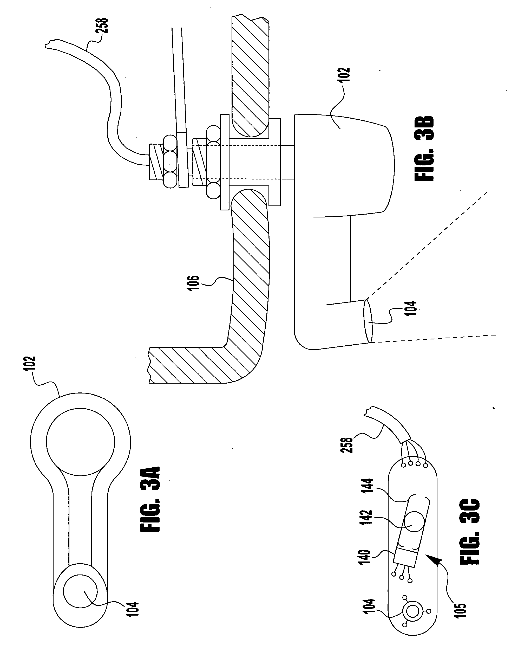
[0024] According to the invention the method further comprises the steps of: using a non-contact proximity sensor to trigger the control circuit to initiate the ventilation activity whenever the proximity sensor detects a user that is close enough to sit on a seat of the toilet; and using a flush detecting sensor to trig

Problems solved by technology

Typically, the problem is resolved by providing a ventilation fan that exhausts air from the toilet enclosu

Method used


Image

  • Toilet ventilation system
  • Toilet ventilation system
  • Toilet ventilation system

Examples


first embodiment

[0053] Backflow Valve Details (First Embodiment)

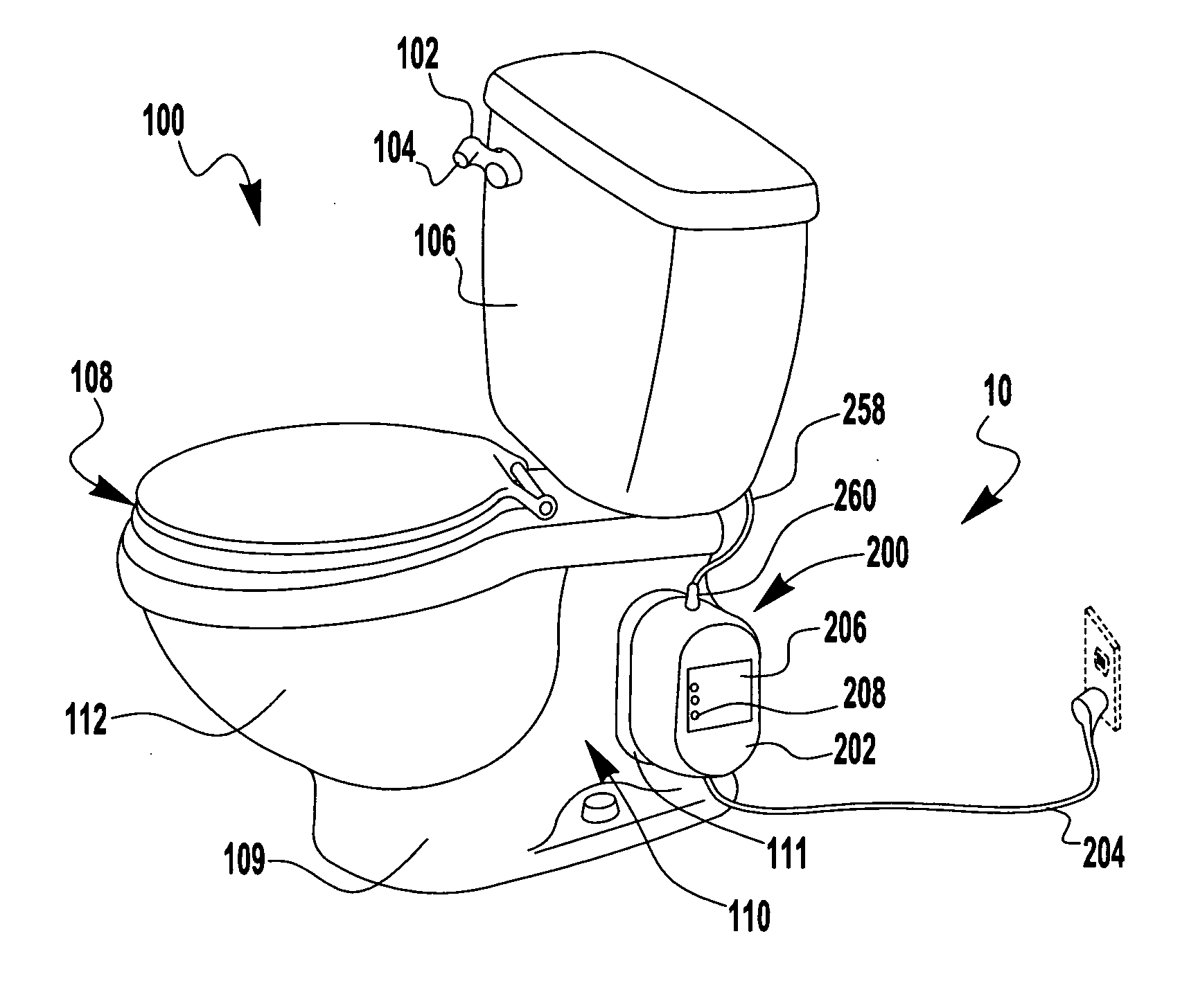
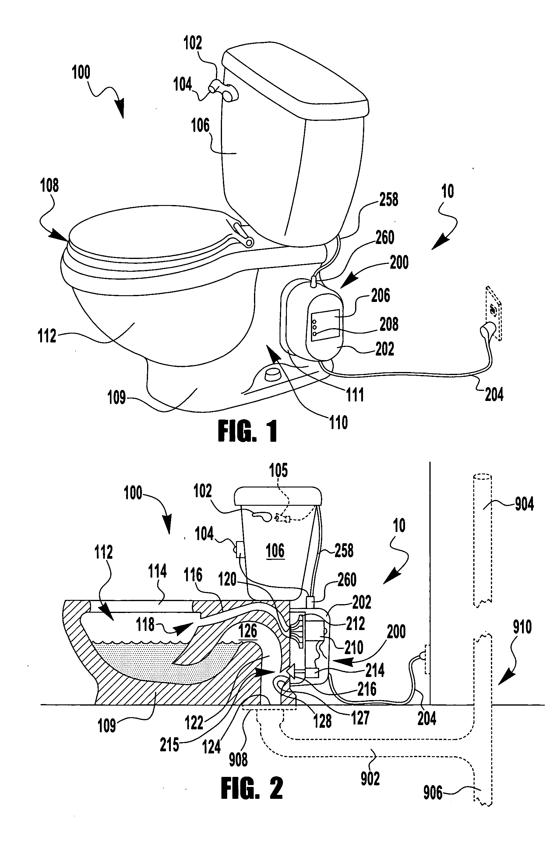
[0054] The blower housing 202 contains a backflow shutoff valve 215 (backflow valve). Its purpose is to close off the ventilation ducts 116, 127 when the blower 200 is not operating, thereby stopping sewer gases from backing out of the ventilated toilet 100. Therefore, closed is the normal state of the backflow valve 215. A stopper for the backflow valve 215 may be a butterfly 217, a poppet 216, a flapper (not shown), or other related valve mechanisms. A design choice should consider one with enough flow capacity to offer minimum resistance to the airflow in the open position. In a first embodiment, the backflow valve 215 is opened, and held open, by an actuator (e.g., a solenoid) 214 when energized. The closed position is maintained by a spring bias in the solenoid 214 or at some other point in the linkage between the solenoid 214 and stopper 216, but preferably not in the airway 230. Between the airway 230 and a sealed motor / electric...

second embodiment

[0056] Backflow Valve Details (Second Embodiment)

[0057] Referring in particular to FIG. 7, a second embodiment of the backflow valve 215′ is shown built into the blower housing 202 which is shown in a partial cross-sectional view with a housing inlet duct 232 portion of the airway 230 leading into the blower unit 200 from the blower intake hole 218 (not shown), and a housing outlet duct 234 portion of the airway 230 leading out of the blower unit 200 to the blower output hole 220 (not shown). The second embodiment of the backflow valve 215′ is simpler than the electromechanical first embodiment backflow valve 215 described hereinabove, and should give equal or better overall performance and be less costly to manufacture.

[0058] The basic operation of the second embodiment of the backflow valve 215′ is to use rotary torque from the blower motor 210 to obtain linear motion to open a port in the airway 230 (e.g., housing inlet duct 232), allowing air to flow into the modified impeller ...


PUM


Abstract

A premium ventilated toilet having an automated toilet ventilation system for removing noxious fumes from a bowl area of the toilet is disclosed. The ventilation system is mostly built-in to the toilet (e.g., ventilation ducts, and sensors) so that it is unobtrusive and attractive looking, however the active parts (e.g., a blower unit containing a blower impeller, a backflow shutoff valve, and electronic control circuitry) are contained in an simple housing that is unobtrusively and removably attached to the surface (preferably on the side) of the toilet base for simplified installation, maintenance, and replacement as needed. Automated operation is enabled by a non-contact occupancy (proximity) sensor and a flush sensor, both preferably built into a flush handle of the toilet. Detection of occupancy causes the ventilation system to operate and flushing turns it off.

Description

CROSS-REFERENCE TO RELATED APPLICATIONS [0001] This application claims the benefit of U.S. Provisional Patent Application No. 60 / 579,011, filed Jun. 12, 2004 by Kenneth A. Lapossy, and which is incorporated in its entirety by reference herein.TECHNICAL FIELD OF THE INVENTION [0002] The present invention relates to water closets (e.g., lavatory), more particularly to those having ventilation for exhaust of noxious fumes, and most particularly wherein the ventilation means are physically associated with a flush toilet. BACKGROUND OF THE INVENTION [0003] It has long been desirable to ventilate noxious fumes from toilet enclosures (witness the half-moon cutout in outhouse doors). It has become even more desirable since the advent of indoor plumbing, as evidenced by U.S. Pat. No. 136,105 (Smith; 1873) which discloses an exhaust flue connected at an upward angle to the bottom of a toilet bowl, before the trap. [0004] Typically, the problem is resolved by providing a ventilation fan that e...

Claims


Application Information

Patent Timeline
IPC IPC(8): E03D9/04E03D9/05
CPCE03D9/05
Inventor LAPOSSY, KENNETH A.
Owner LAPOSSY KENNETH A
Why Eureka
Try Eureka