
Method and apparatus for recognizing an object within an image

a technology of object recognition and image, applied in the field of automatic detection and recognition of objects, can solve the problems of difficult to overcome using conventional image processing techniques, limited recognition of objects within images, etc., and achieve the effect of enhancing the ability to detect objects within images

Inactive Publication Date: 2005-12-15
ITT MFG ENTERPRISES LLC
View PDF4 Cites 74 Cited by
  • Summary
  • Abstract
  • Description
  • Claims
  • Application Information

AI Technical Summary

Benefits of technology

[0012] Another object of the present invention is to facilitate operator interpretation of noisy, partially obstructed images while preserving operator confidence in enhanced / processed images.
[0024] The methods and apparatus described here provide a highly accurate, automated approach for detecting and recognizing objects of interest, or target objects, within a generated image. The approach described is compatible with a wide variety of generated image types and can be trained to detect a wide variety of objects within the generated images, thereby making the object detection and recognition system capable of supporting a large number of diverse operational missions. The described methods and apparatus support fully automated detection of target objects within a generated image and / or can assist human operators by automatically identifying objects of interest within a generated image. The method and apparatus is capable of assessing generated images for objects of interest in real-time, or near real-time.

Problems solved by technology

Although significant advances have been made with respect to generating images using such technologies, relatively few advances have been made with respect to automatically interpreting the content of generated images.
Efforts to automatically detect and recognize objects of interest, or target objects, within a generated image typically encounter a wide variety of obstacles that have proven difficult to overcome using conventional image processing techniques.
In addition, a view of an object within an image may be partially blocked and / or cluttered due to background noise and / or objects in proximity to the object of interest.
Further, the contraband object may be oriented within a closed package in a manner that results in a non-conventional view of the object.
Unfortunately, such template matching is sensitive to changes in object rotation and changes in object scale.
Further, template matching is a computationally complex process and has difficulty detecting objects within cluttered and / or partially obstructed views.
Given the current state of conventional object detection / recognition techniques, attempts to automate object detection and to automate recognition of detected objects often result in a high number of undetected / unrecognized target objects and a high number of false target object recognitions.
As a result of such poor performance, generated images are typically interpreted by technicians who have been specifically trained to interpret one or more types of generated images and to detect / recognize objects within a generated image.
The need for trained and / or experienced personnel to effectively operate conventional object detection and recognition systems greatly increases the operational costs of organizations that use such conventional systems.
Further, approaches that rely upon visual analysis by human operators remain susceptible to human error as a result of operator fatigue and / or lapses in concentration.
For example, in high volume environments such as personnel, luggage and cargo inspections at busy airports, seaports and railway stations, attempts to rapidly assess image content based upon operator analysis of generated image have proven to be highly susceptible to human error.

Method used


Image

  • Method and apparatus for recognizing an object within an image
  • Method and apparatus for recognizing an object within an image
  • Method and apparatus for recognizing an object within an image

Examples


Embodiment Construction

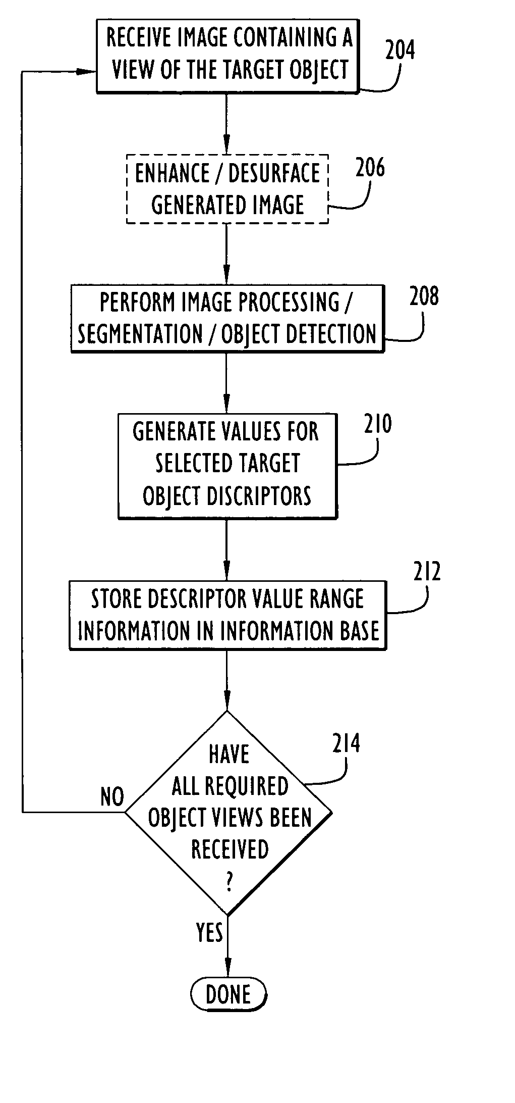
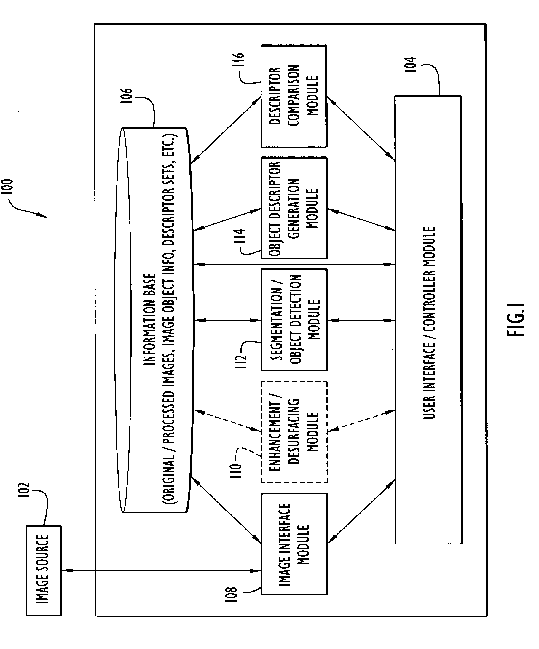
[0036]FIG. 1 presents a block diagram of an object recognition system in accordance with an exemplary embodiment of the present invention. As shown in FIG. 1, object recognition system 100 may include a user interface / controller module 104 in communication with an information base 106. Object recognition system 100 may further include an image interface module 108, an optional enhancement / de-surfacing module 110, a segmentation / object detection module 112, an object descriptor generation module 114, and a descriptor comparison module 116. Each of these modules may communicate with information base 106, either directly or via user interface / controller module 104.

[0037] Object recognition system 100 may receive an image from an external image source 102 via image interface module 108 in accordance with operator instructions received via user interface / controller module 104 and may store the received image in information base 106. Once an image has been received / stored, object recogni...


PUM


Abstract

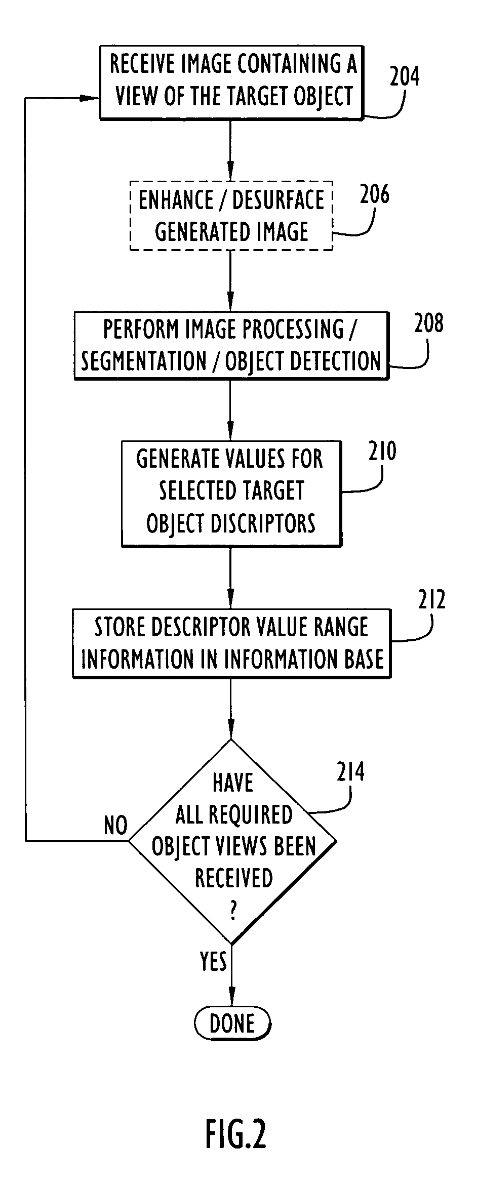
A method and apparatus is described for detecting and recognizing an object within a generated image regardless of the aspect view angle of the object within the image. An object may be recognized by comparing descriptor values determined for the detected object with descriptor values and / or value ranges stored in an information base for different aspect view angles of a plurality of objects. A novel desurfacing approach may be use to remove image surface distortions unrelated to objects within the image. A novel graphical user interface may be used to improve user interaction and control of the object recognition process. The method and apparatus described may be used to detect objects within images generated by a wide variety of imaging systems. For example, concealed explosive devices may be detected by configuring the apparatus to recognize views of a conventional blasting cap's dense explosive filler within x-ray generated images.

Description

BACKGROUND OF THE INVENTION [0001] 1. Field of the Invention [0002] . The present invention pertains to automated detection and recognition of objects. In particular, the present invention pertains to the use of image processing and image analysis techniques to detect and recognize a view of an object within an image. [0003] 2. Description of the Related Art [0004] Recent advances in imaging technologies have resulted in the ability to quickly and easily generate images, or imagery data, in support of a wide variety of applications. For example medical imaging technologies such as X-rays, computer aided tomography, and magnetic resonance imaging (MRI) allow high resolution images to be generated of areas deep within the human body without invasive procedures. Further, earth sciences imaging technologies such as ship-board sonar and aircraft / spacecraft based high-resolution radar and multi-spectrum photography may be used to generate detailed images of the ocean floor, areas of agric...

Claims


Application Information

Patent Timeline
IPC IPC(8): G06K9/00
CPCG06K9/00208G06V20/647
Inventor SLAMANI, MOHAMED ADELSLAMANI, AHMED A.
Owner ITT MFG ENTERPRISES LLC
Learn More