Refrigerating machine

Inactive Publication Date: 2005-12-22
SANYO ELECTRIC CO LTD +1
View PDF1 Cites 5 Cited by
  • Summary
  • Abstract
  • Description
  • Claims
  • Application Information

AI Technical Summary

Benefits of technology

[0006] Therefore, an object of the present invention is to provide a refrigerating machine which can keep or enhance the performance thereof even when

Problems solved by technology

This type of refrigerating machine has a problem that when the temperature of refrigerant at the exit of a heat exchanger used as a radiator (hereinafter referred to as “radiation side heat exchanger”) increases, the specific enthalpy of the refrigerant at the exist of the rad

Method used


Image

  • Refrigerating machine
  • Refrigerating machine
  • Refrigerating machine

Examples


Example

[1] First Embodiment

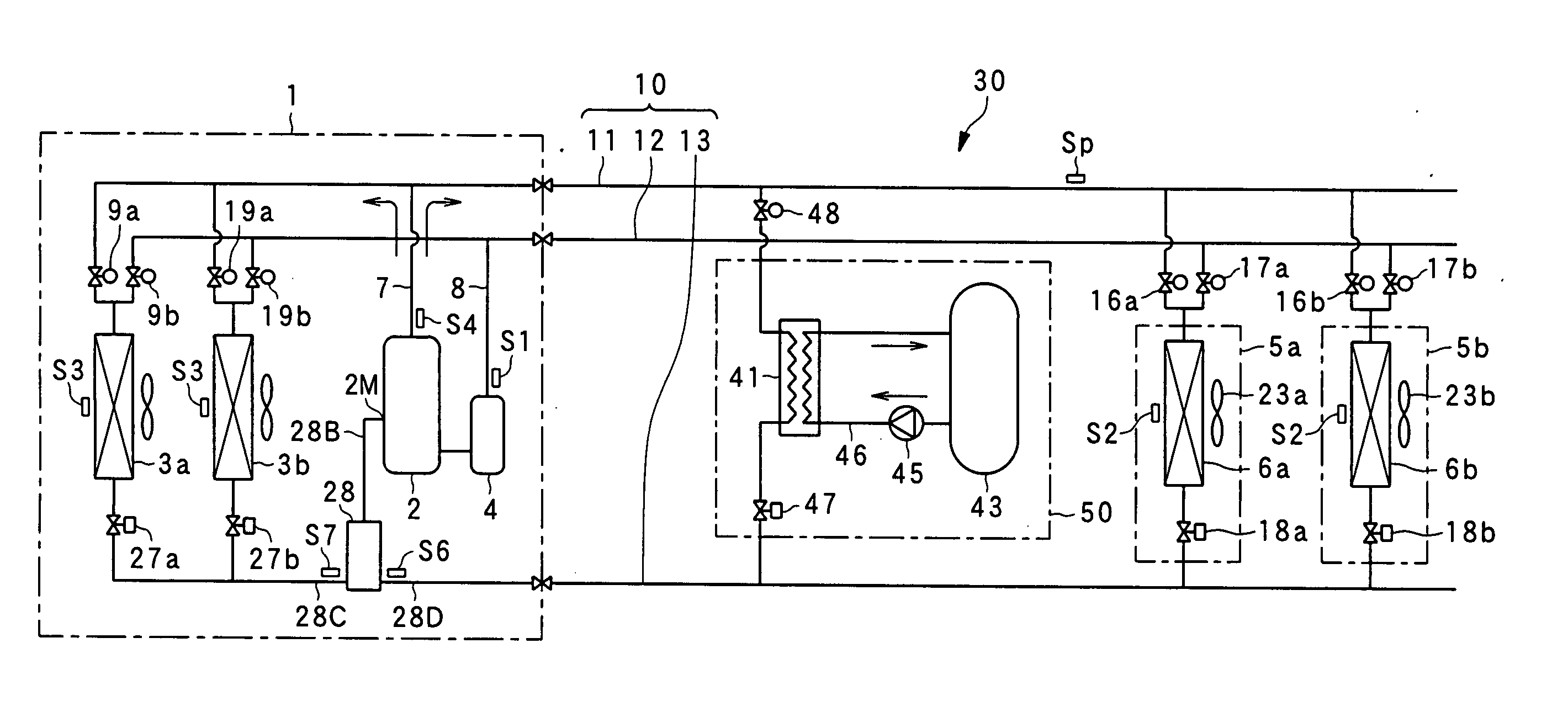
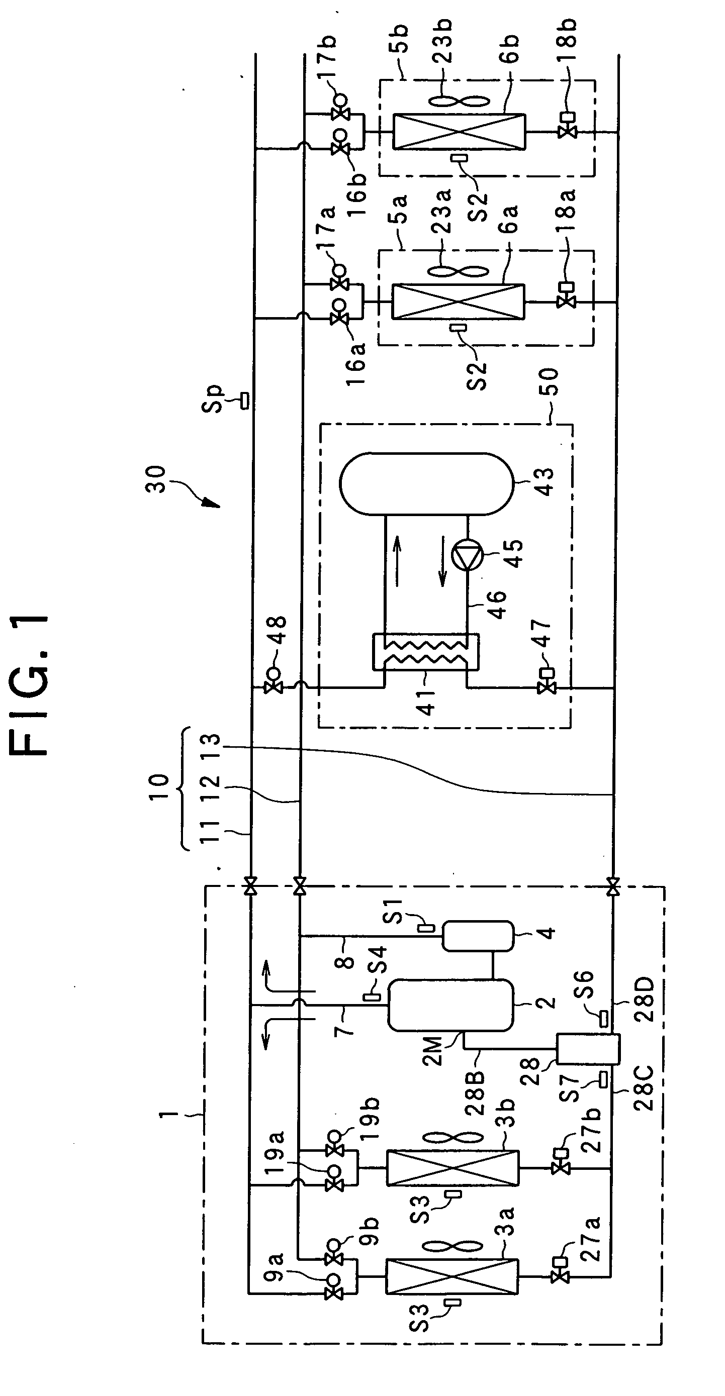
[0022]FIG. 1 is a refrigerant circuit diagram showing an embodiment of a refrigerating machine according to the present invention.

[0023] A refrigerating machine 30 is equipped with an outdoor unit 1 having a compressor 2, outdoor heat exchangers 3a, 3b and outdoor expansion valves 27a, 27b, an indoor unit 5a having an indoor heat exchanger 6a and an indoor expansion valve 18a, an indoor unit 5b having an indoor heat exchanger 6b and an indoor expansion valve 18b, and a hot-water stocking unit 50 having a hot-water stocking heat exchanger 41, a hot-water stocking tank 43, a circulating pump 45 and an expansion valve 47.

[0024] The outdoor unit 1, the indoor units 5a, 5b and the hot-water stocking unit 50 are connected to one another through an inter-unit pipe 10, and the refrigerating machine 30 can carry out cooling operation or heating operation in the indoor units 5a, 5b at the same time or carry out both cooling operation and heating operation in the indoor...

Example

[2] Second Embodiment

[0099]FIG. 5 is a refrigerant circuit diagram showing the main part of a refrigerating machine according to a second embodiment. In FIG. 5, the same parts as the first embodiment are represented by the same reference numerals.

[0100] The difference of a refrigerating machine 30-1 of the second embodiment from the refrigerating machine 30 of the first embodiment resides in that anti-freezing heat exchangers 60a, 60b for anti-freezing the liquid-phase refrigerant passing through the heat exchange circuit 28 under heating operation are provided integrally with the outdoor heat exchangers 3a, 3b serving as the heat source side heat exchangers respectively so as to be located between the outdoor expansion valve 27a and the heat exchange circuit 28a and between the outdoor expansion valve 27b and the heat exchange circuit 28, respectively.

[0101] Next, the operation of the refrigerating machine under heating operation will be described.

[0102] When the heating opera...


PUM


Abstract

A refrigerating machine equipped with a compressor has an intermediate-pressure portion in which refrigerant having intermediate pressure higher than the pressure of the refrigerant at the suction side of the compressor and lower than the pressure of the refrigerant at the discharge side of the compressor is allowed to be introduced, and a heat exchange circuit formed between a heat-source side heat exchanger and a using side heat exchanger. The heat exchange circuit branches the refrigerant flowing from any one of the heat exchangers to the other heat exchanger, carries out heat exchange between one branched refrigerant and the other branched refrigerant or the refrigerant before the branching so that the one branched refrigerant is set to gas-phase refrigerant, and the gas-phase refrigerant thus achieved is led to any one of the intermediate-pressure portion and refrigerant suction pipe of the compressor.

Description

BACKGROUND OF THE INVENTION [0001] 1. Field of the Invention [0002] The present invention relates to a refrigerating machine that has an outdoor unit and a plurality of indoor units and enables these plural indoor units to carry out heating operation and cooling operation in a mixing style. [0003] 2. Description of the Related Art [0004] There is generally known a refrigerating machine in which an outdoor unit is connected to a plurality of indoor units through an inter-unit pipe comprising a high-pressure gas pipe, a low-pressure gas pipe and a liquid pipe so that one of cooling operation and heating operation can be carried out in the plural indoor units at the same time or both cooling operation and heating operation can be carried out in the plural indoor units in a mixing style at the same time (see Japanese Patent No. 2804527). In this specification, it is assumed that the refrigerating machine contains a heat pump. [0005] This type of refrigerating machine has a problem that ...

Claims


Application Information

Patent Timeline
IPC IPC(8): F25B1/00F25B1/10F25B9/00F25B13/00F25B15/00F25B40/00
CPCF25B1/10F25B9/008F25B13/00F25B40/00F25B2400/24F25B2313/007F25B2313/0231F25B2313/02791F25B2400/13F25B2309/061
Inventor OTAKE, MASAHISAMUKAIYAMA, HIROSHISATO, KOJISEKIGAMI, KUNIESHIKICHI, KAZUAKI
Owner SANYO ELECTRIC CO LTD
Why Eureka
Try Eureka