Blocking devices for hollow structures

Inactive Publication Date: 2005-12-22
KYOWA SANGYO +1
View PDF25 Cites 41 Cited by
  • Summary
  • Abstract
  • Description
  • Claims
  • Application Information

AI Technical Summary

Benefits of technology

[0014] Therefore, the expandable member may be reliably molded so as to have a desired configuration. At the same time, the flexed portion may be formed integrally with the expandable member. As a result, the productivity of the expandable member having a constriction absorbing portion can be

Problems solved by technology

As a result, the blocking device may reliably

Method used


Image

  • Blocking devices for hollow structures
  • Blocking devices for hollow structures
  • Blocking devices for hollow structures

Examples


first representative embodiment

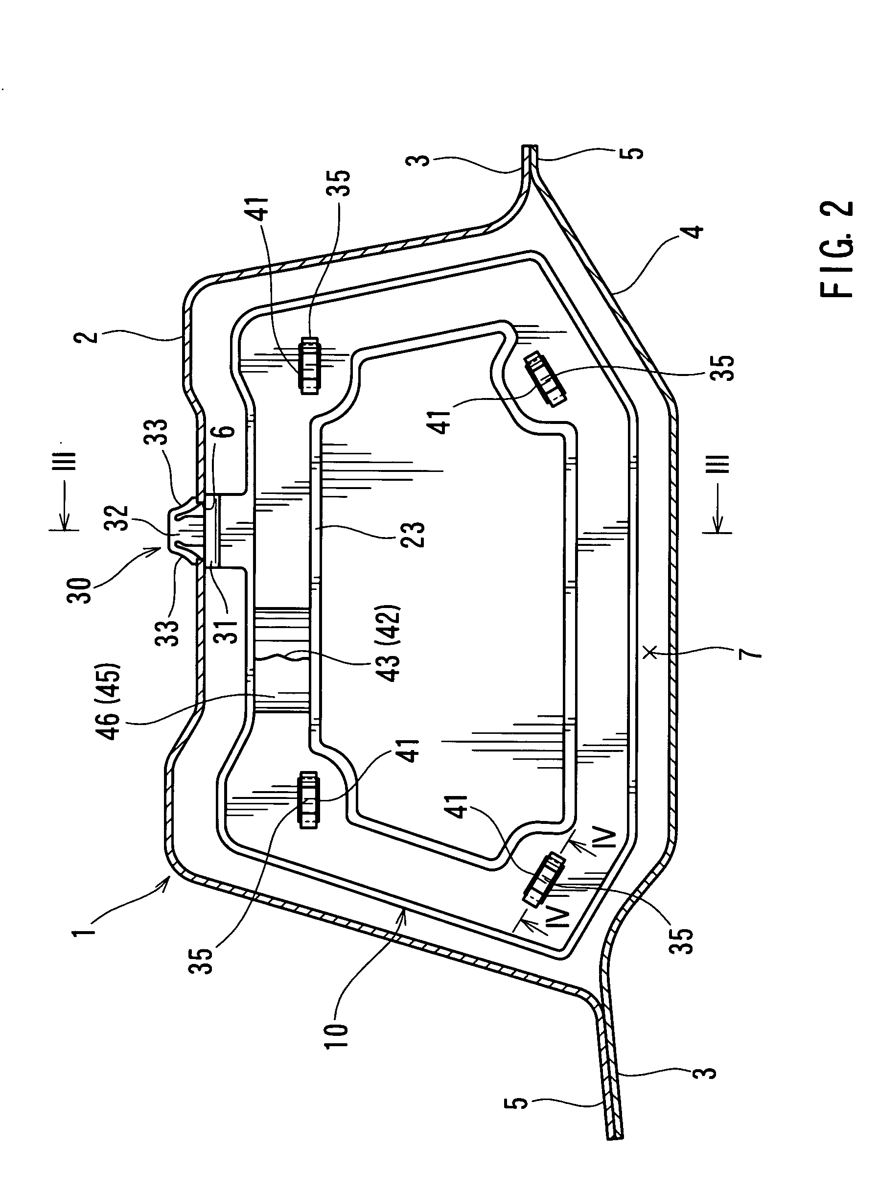
[0034] A first representative embodiment will now be described with reference to FIGS. 1 to 9. Referring to FIG. 2, a hollow panel 1 has an inner panel 2 and an outer panel 4. The inner panel 2 and the outer panel 4 respectively have flanges 3 and 5 that are joined together by a spot-welding process to define a space 7, which has a closed cross-sectional area. For example, the hollow panel 1 may be a pillar, a rocker panel, or a roof-side panel of an automobile body. A non-circular mounting hole 6 is formed in the inner panel 2 at a predetermined position and extends throughout the thickness of the inner panel 2. A mounting clip 30 is fitted into the mounting hole 6 so as not to rotate relative thereto. For example, the mounting hole 6 may have an oval configuration, an elliptical configuration, or a rectangular configuration.

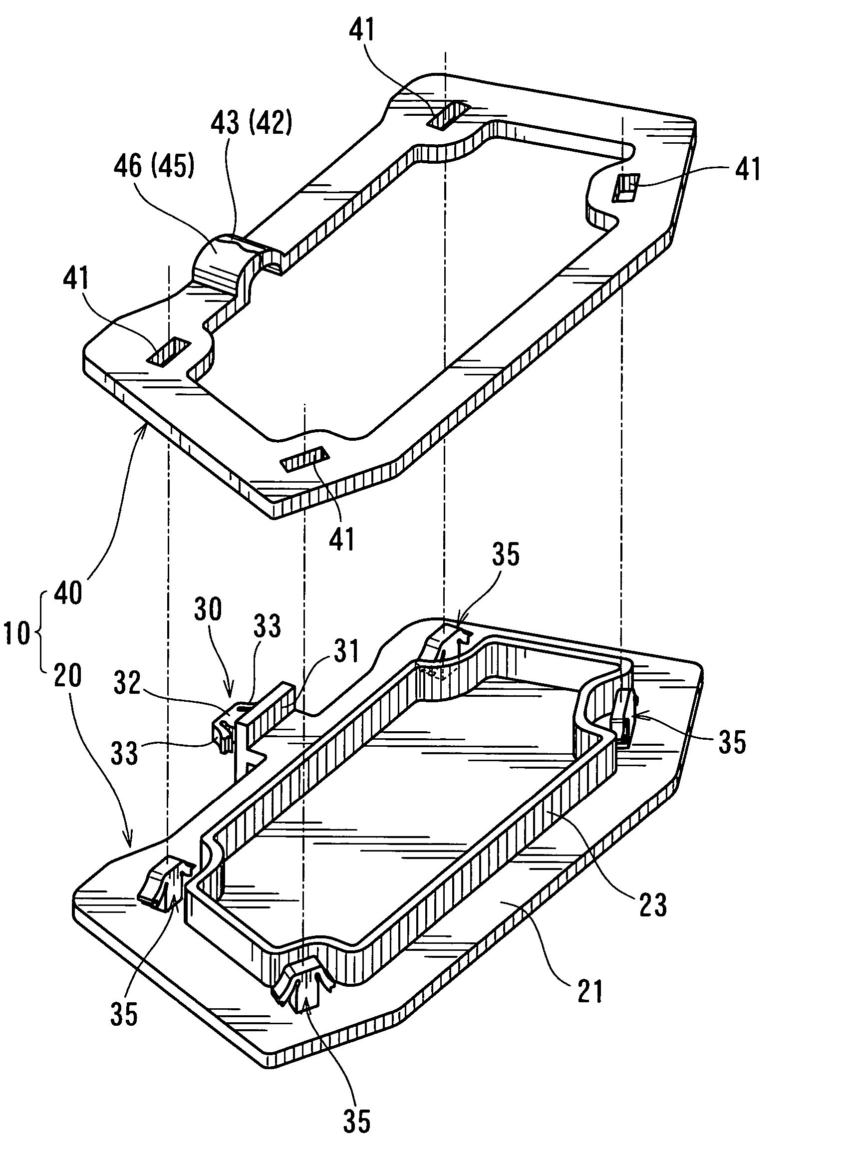
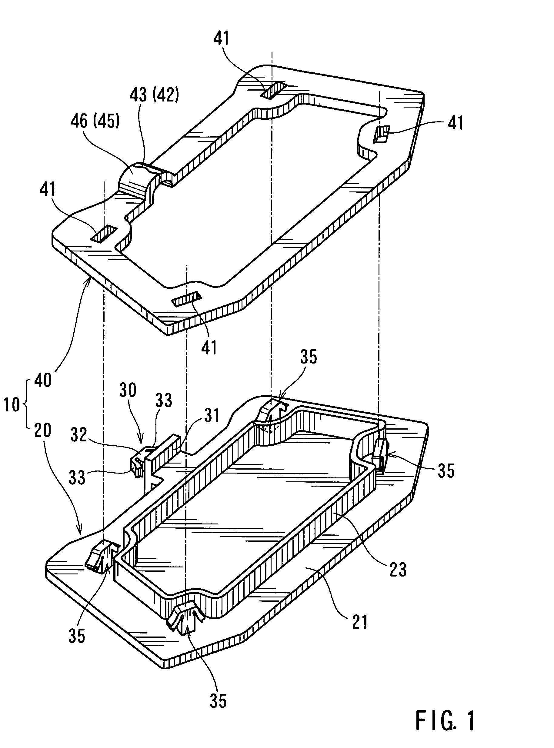
[0035] As shown in FIGS. 1 to 3, a representative blocking device 10 is disposed within the space 7 of the hollow panel 1 and includes a holder 20 and an expa...

second representative embodiment

[0051] A second representative embodiment will now be described with reference to FIGS. 10 and 11. The second representative embodiment is a modification of the first representative embodiment. Therefore, in FIGS. 10 and 11, like members are given the same reference numerals as in the first representative embodiment and the description of these members may not be repeated.

[0052] Referring to FIGS. 10 and 11, a hollow panel 101 defines a space 107 having a substantially eyeglass-shaped configuration in cross-section. A blocking device 110 has a holder 120 and an expandable member 140. Similar to the first representative embodiment, the holder 120 is mounted within the space 107. In addition, the expandable member 140 is supported by the holder 120 and is expandable to form a foam member that blocks or substantially closes the space 107 when heated. Further, the holder 120 is made of heat resisting synthetic resin and includes the holder plate 21 and two mounting clips 30.

[0053] The...


PUM


Abstract

A blocking device for mounting within a space defined within a hollow structure includes a holder and an expandable member. The holder is adapted to be mounted within the space. The expandable member is supported on the holder and is expandable by heat to form a foam member in order to block or substantially close the space. The holder includes a holder plate extending substantially perpendicular to the longitudinal axis of the space and supporting at least one side of the expandable member. The expandable member includes a constriction absorbing portion that is deformed so as to absorb potential constriction of the expandable member at the beginning of the expansion process of the expandable member.

Description

[0001] This application claims priority to Japanese patent application serial number 2004-179703, the contents of which are incorporated herein by reference. BACKGROUND OF THE INVENTION [0002] 1. Field of the Invention [0003] The present invention relates to blocking devices for hollow structures. In particular, the present invention relates to blocking devices for improving the damping and sound insulating properties of hollow panel structures, such as pillars, rocker panels, and roof side panels of automobile bodies. The hollow panel structures are each formed by a plurality of panels to have a closed cross-sectional area. [0004] 2. Description of the Related Art [0005] A known blocking device has a holder mounted within a space defined within a hollow structure and an expandable member that is supported by the holder. The expandable member may be externally heated to expand so as to form a foam member. The holder includes a holder plate and a mounting device for mounting to the h...

Claims


Application Information

Patent Timeline
IPC IPC(8): B62D29/00F16F15/00
CPCB60R13/08B62D29/002B60R13/0815
Inventor ITO, TAKAHISA
Owner KYOWA SANGYO
Why Eureka
Try Eureka