
Radiator hose bracket

a technology for mounting brackets and radiator hoses, which is applied in the direction of kitchen equipment, domestic applications, and stands/trestles. it can solve the problems of premature wear of radiator hoses, possible leakage of radiator hoses, and the catenary movement of radiator hoses of automotive vehicles

Inactive Publication Date: 2005-12-22
NEWFREY
View PDF14 Cites 13 Cited by
  • Summary
  • Abstract
  • Description
  • Claims
  • Application Information

AI Technical Summary

Benefits of technology

The present invention provides a radiator hose bracket for vehicles that allows for easy installation and secure retention of the radiator hose. The bracket includes an injection molded main bracket member with a C-shaped hose clamping portion that allows for free movement of the hose. The bracket is designed to prevent rotation and includes anti-rotation features. The technical effects of this invention are improved installation and secure retention of the radiator hose, reducing the risk of leaks and damage to the engine.

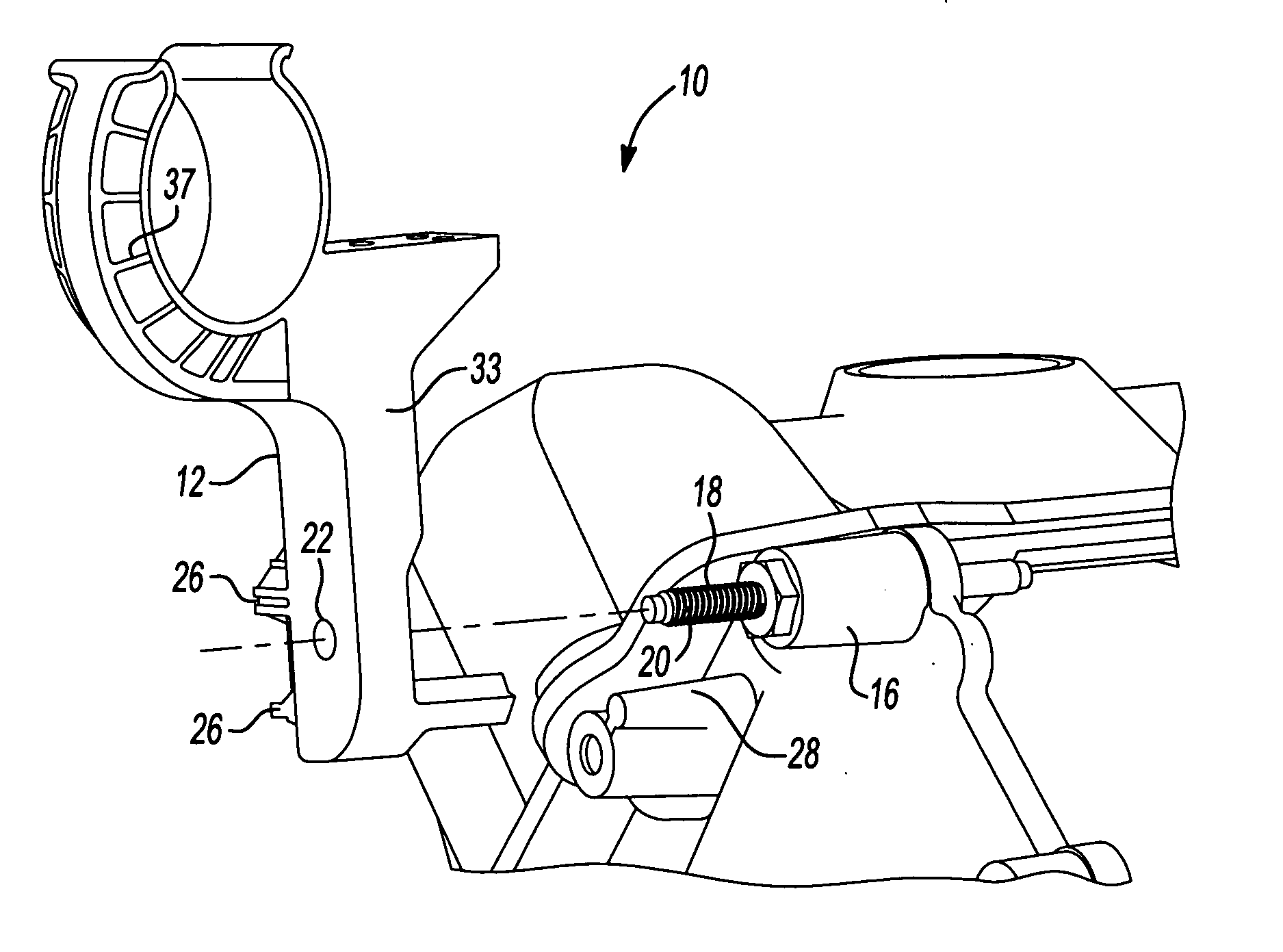
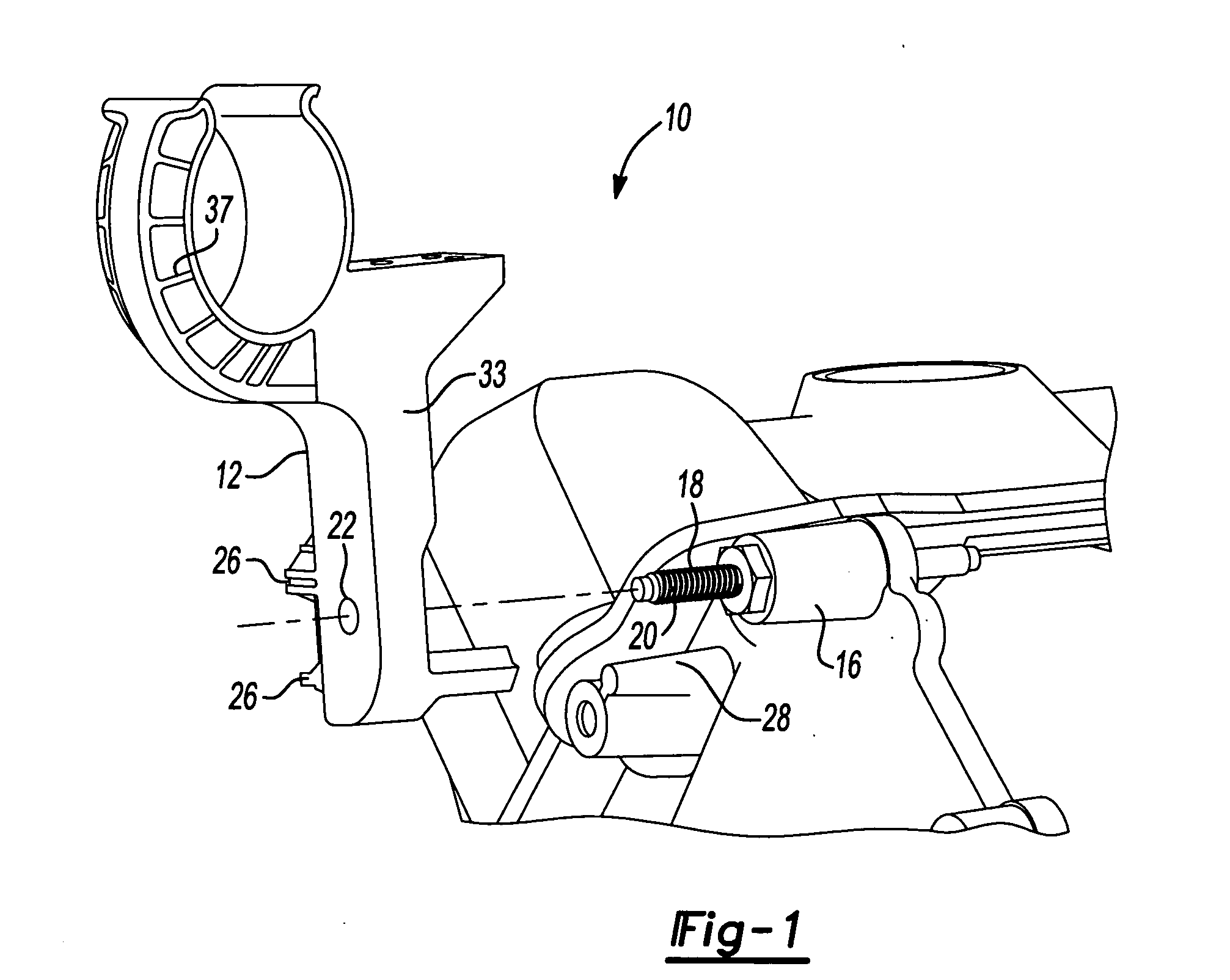
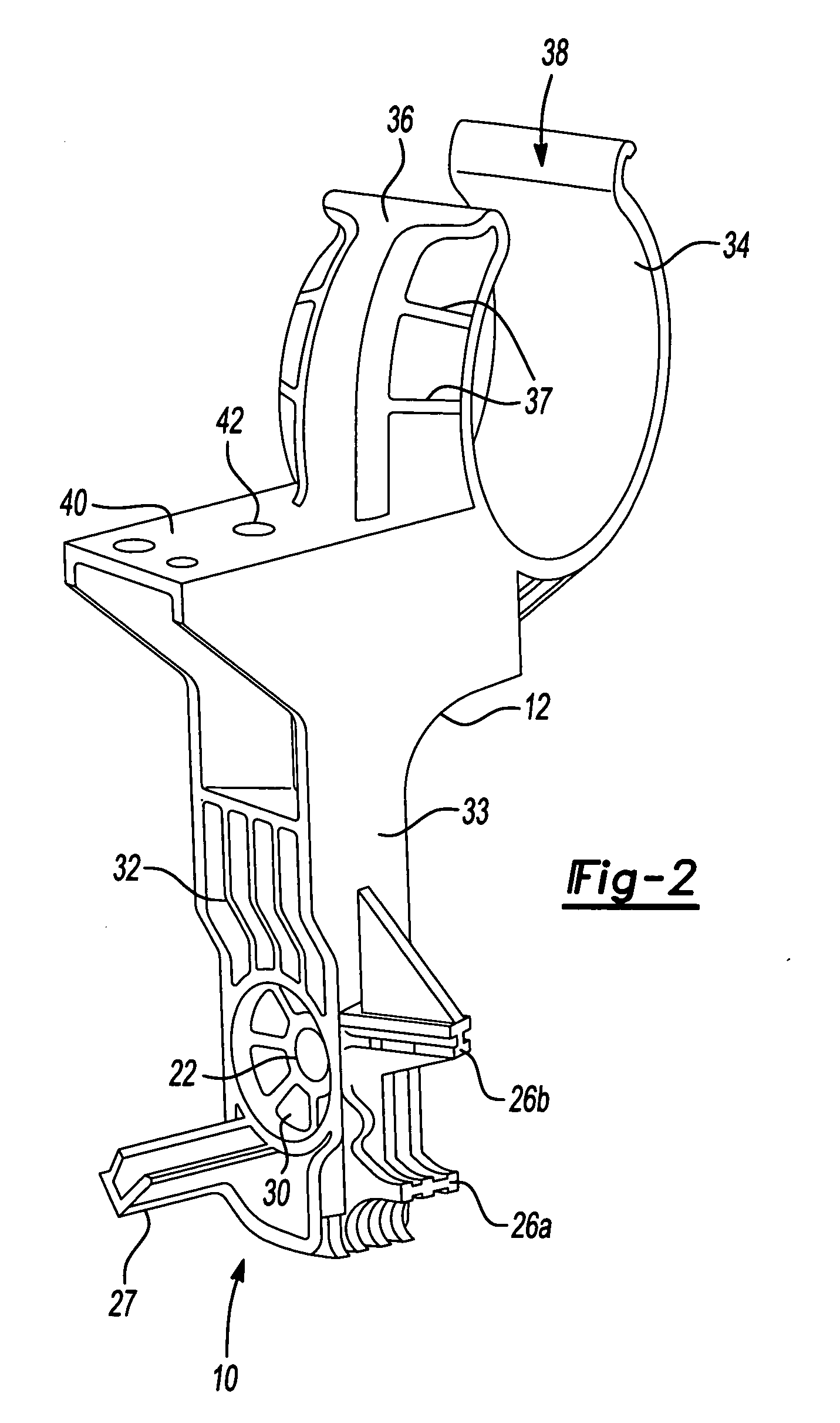
Problems solved by technology

The technical problem addressed in this patent text is the need for a radiator hose bracket that can securely hold the hose in place during vehicle operation, preventing premature wear and leakage while also preventing damage to nearby components. Existing supports have failed to provide a reliable and positive solution for this problem.

Method used


Image

  • Radiator hose bracket
  • Radiator hose bracket
  • Radiator hose bracket

Examples


Embodiment Construction

[0013] The following description of the preferred embodiment is merely exemplary in nature and is in no way intended to limit the invention, its application, or uses.

[0014] Referring to the figures, a radiator hose bracket assembly 10 generally includes an injection-molded main bracket member 12 for restraining the movement of radiator hose 14 of a vehicle. Main bracket member 12 encapsulates radiator hose 14 of the vehicle to restrain such movement, which might stress radiator hose 14 mounts or damage radiator hose 14 by allowing it to wear against the design environment, such as the radiator fan, supports, or other engine components.

[0015] Main bracket member 12 of radiator hose bracket assembly 10 is mounted to an engine block 16 via a fastener 18. More specifically, as seen in FIG. 1, fastener 18 is a double-ended threaded fastener that is threadedly engaged with engine block 16 and further provides an extending threaded portion 20. Main bracket member 12 includes a mounting a...


PUM


Abstract

A radiator hose bracket for retaining a radiator hose relative to an engine block of a vehicle. The radiator hose bracket includes an injection molded main bracket member having a C-shaped hose clamping portion. The C-shaped hose clamping portion is sized to laterally retain the radiator hose and permit free longitudinal movement of the radiator hose. An aperture extends through the main bracket member for coupling the main bracket member to the engine block. Anti-rotation features are integrally formed with the main bracket member to prevent rotation of the main bracket member relative to the engine block.

Description


Claims


Application Information

Patent Timeline
Owner NEWFREY
Learn More