Object region data describing method and object region data creating apparatus

Inactive Publication Date: 2005-12-22
MAXELL HLDG LTD
View PDF9 Cites 27 Cited by
  • Summary
  • Abstract
  • Description
  • Claims
  • Application Information

AI Technical Summary

Benefits of technology

[0009] In accordance with the purpose of the invention, as embodied and broadly described, the invention is directed to an object region data describing method and an object region data creating apparatus which enable the region of a desired object in an image to be described in a small

Problems solved by technology

Thus, there arises a problem in that the quantity of data cannot be reduced.
On the other hand, complex compression and decoding processes are required.
Stated another way, the mask image is not suitable for identifying the object region in the video since it has a large quantity of data.
The compressed mask image has a draw

Method used


Image

  • Object region data describing method and object region data creating apparatus
  • Object region data describing method and object region data creating apparatus
  • Object region data describing method and object region data creating apparatus

Examples


first embodiment

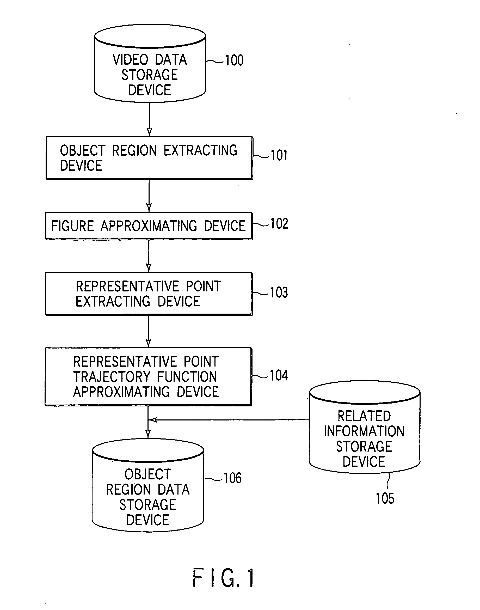
[0113]FIG. 1 shows the configuration of an object region data creating apparatus (or an object region data converting system) according to the first embodiment of the present invention.

[0114] As shown in FIG. 1, the object region data creating apparatus comprises a video data storage device 100, a region extracting device 101, a region figure approximating device 102, a figure representative point extracting device 103, a representative point trajectory function approximating device 104, and an object region data storage device 106. It may further comprise a related information storage device 105.

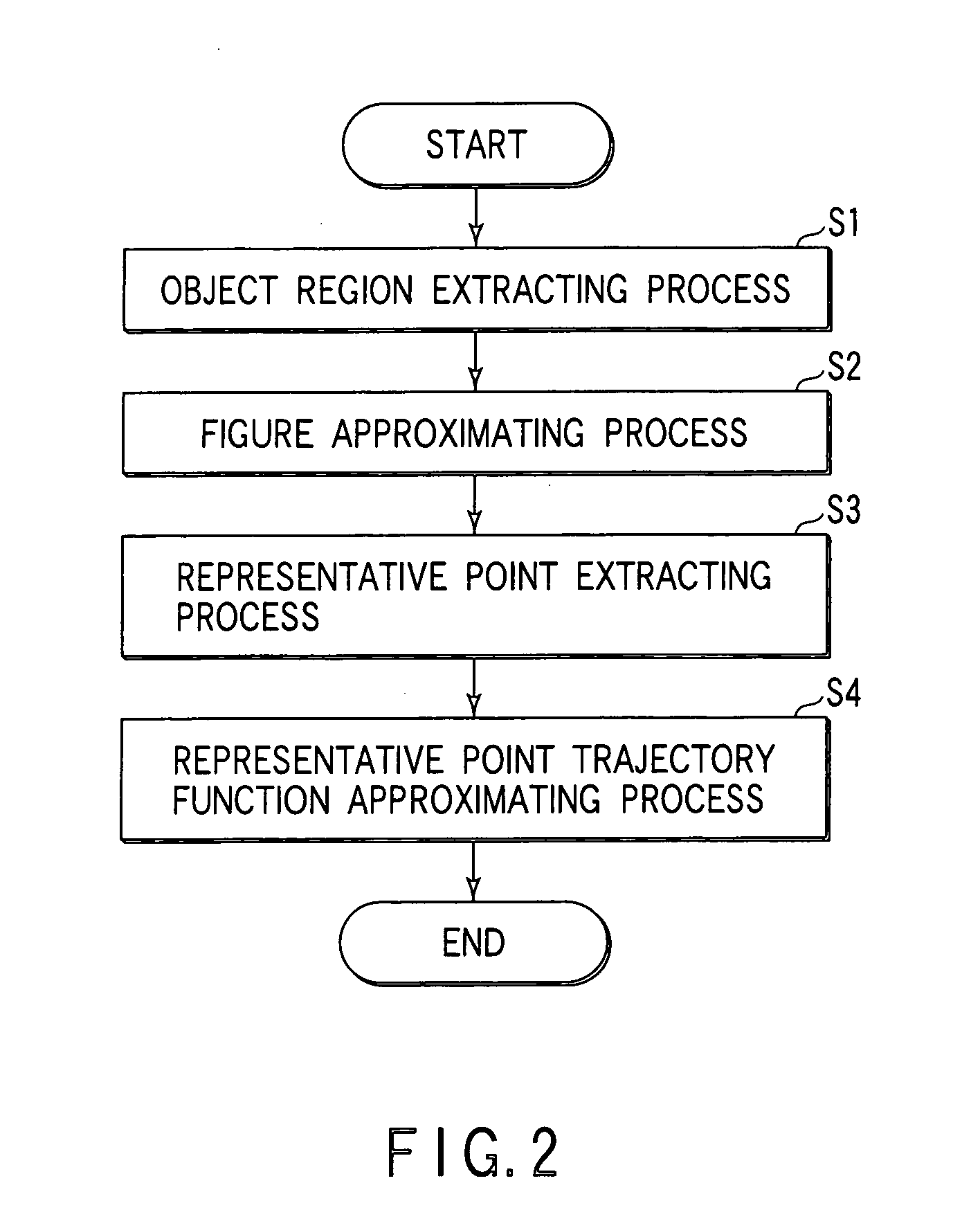
[0115]FIG. 2 is a flowchart for processing in the object region data creating apparatus.

[0116] The video data storage device 100, which stores video data, is composed of, for example, a hard disk, an optical disk, or a semiconductor memory.

[0117] The region extracting device 101 extracts a partial region of the video data (step S1). The partial region is generally the object region, suc...

second embodiment

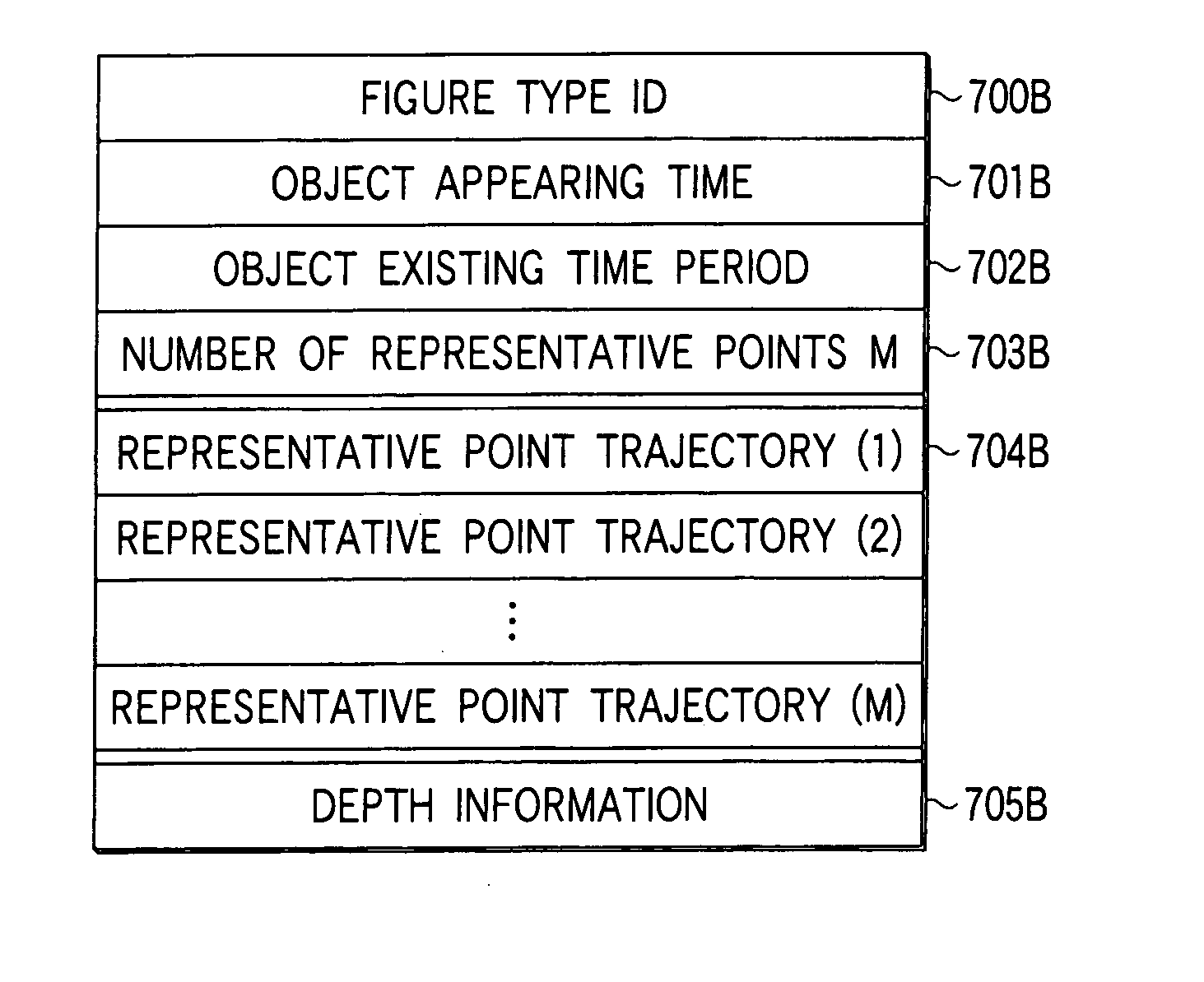
[0224] A second embodiment of the present invention is such that information on the direction of depth, in addition to the two-dimensional information on the screen, is included in the object region data about an object in the image in the first embodiment. Explanation will center on the difference between the second embodiment and the first embodiment.

[0225] In the second embodiment, the object region data creating apparatus of the first embodiment has to be further provided with a processing device 108 for obtaining information about the direction of depth (hereinafter, referred to as depth information). The depth information processing device 108 is connected between the video data storage device 100 and the representative point trajectory function approximating device 104, as shown in FIG. 15.

[0226] There are two methods of giving depth information: one method of giving depth information in consecutive values (Z-coordinates) and the other method of giving depth information in ...

third embodiment

[0252] A third embodiment of the present invention is such that display flag information is further included in the object region data in the video in the first or second embodiment. The display flag information is related to a display flag that indicates whether an object (or part of the object) is visible or invisible because it hides behind another object. Explanation will center on the difference between the third embodiment and the first or second embodiment.

[0253] In the third embodiment, a process related to the display flag is carried out at, for example, the representative point trajectory function approximating device 104.

[0254] For instance, as shown in FIG. 26A to FIG. 26C, when there are a plurality of objects in the video, an object 2101 may often disappear behind another object 2102 and appear from behind the object 2102. To describe this state, display flag information is added to the object region data.

[0255] There are two methods of giving the display flag: one ...


PUM


Abstract

An object region data describing method of describing information about the object region in an image over a plurality of frames determines the region of a target object in an image using an approximate function that approximates the trajectory obtained by arranging, in the direction of frame advance, one representative point of an approximate figure for the object region and the difference values for determining the other representative points and describes information about the object region using a parameter for the function.

Description

CROSS-REFERENCE TO RELATED APPLICATIONS [0001] This application is based upon and claims the benefit of priority from the prior Japanese Patent Application No. 2000-138571, filed May 11, 2000, the entire contents of which are incorporated herein by reference. BACKGROUND OF THE INVENTION [0002] The present invention relates to an object region data describing method of describing information about the object region in a video and an object region data creating apparatus. [0003] Hyper media are configured such that related information called a hyper link is given in between mediums, such as videos, sounds or texts, to permit mutual reference. When videos are mainly used, related information has been provided for each object which appears in the video. When the object is specified, related information (text information or the like) is displayed. The foregoing structure is a representative example of the hyper media. The object in the video is expressed by a frame number or a time stamp...

Claims


Application Information

Patent Timeline
IPC IPC(8): G06T7/20
CPCG06T7/2033G06T2207/30236G06T2207/10016G06T7/2046G06T7/246G06T7/251G06T7/60
Inventor HORI, OSAMUKANEKO, TOSHIMITSUYAMAMOTO, KOJIMITA, TAKESHIMASUKURA, KOICHI
Owner MAXELL HLDG LTD
Why Eureka
Try Eureka