
System and method for auto-threshold adjustment for phasing

Active Publication Date: 2005-12-22
VIDEOJET TECH INC
View PDF17 Cites 14 Cited by
  • Summary
  • Abstract
  • Description
  • Claims
  • Application Information

AI Technical Summary

Problems solved by technology

This process is inconvenient, time-consuming, and inaccurate for printer users.
Additionally, positioning a sensor in the ink catcher introduces additional interference in charge measurements due to the catcher and distance from a nozzle originating the ink stream.
Furthermore, it is difficult to isolate individual ink drops in the ink catcher.

Method used


Image

  • System and method for auto-threshold adjustment for phasing
  • System and method for auto-threshold adjustment for phasing
  • System and method for auto-threshold adjustment for phasing

Examples


Embodiment Construction

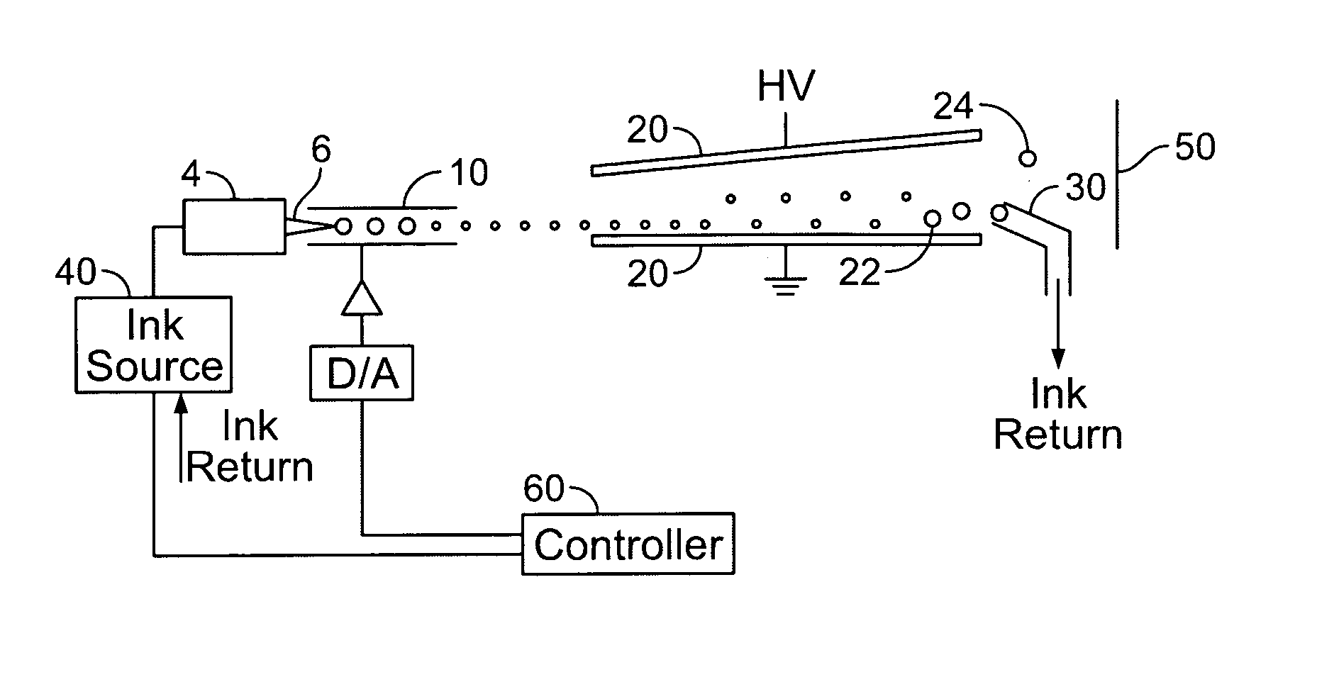
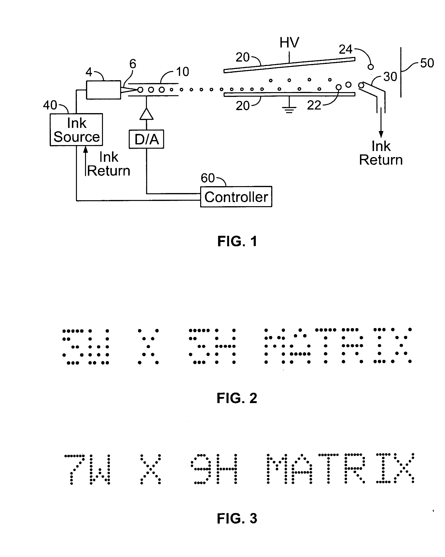
[0024] According to an embodiment shown in FIG. 1, a continuous ink jet printer 1 includes a print head with a drop generator 4 which receives ink from an ink source 40. The drop generator incorporates a piezoelectric oscillator which creates perturbations in the ink flow at a nozzle 6. Regular sized and spaced drops are accordingly emitted from the nozzle. The drops pass through a charging tunnel 10, where a different charge can be applied to each drop. This charge determines the degree of deflection as the drop passes between a pair of deflection plates 20 between which a substantially constant electric field is maintained. Uncharged or slightly charged drops 22 pass substantially undeflected to a catcher 30, and are recycled to ink source 40. Charged drops 24 are projected toward a substrate 50 and are deflected so as to have a trajectory striking the latter which moves past the print head in the horizontal direction. The level of charge applied to the drop controls its vertical ...


PUM


Abstract

Certain embodiments provide a system and method for auto-threshold adjustment using a continuous ink jet printer. An embodiment of a system includes a nozzle for producing ink drops from an ink stream, a sensor positioned with respect to the nozzle for measuring charge from the ink drops to generate a charge signal, a peak detector for detecting peaks in the charge signal, and a threshold storage device for adjusting the threshold based on a number of detected peaks. In an embodiment, the threshold storage device stores the threshold. The threshold storage device may be a digital potentiometer, for example. The system may also include a comparator comparing the charge signal to the threshold. The comparator may select between the threshold and a standard reference signal to compare to the charge signal.

Description

RELATED APPLICATIONS [0001] The present application relates to, and claims priority from, U.S. Provisional Application No. 60 / 581,239 filed on Jun. 17, 2004, and entitled “System and Method for Auto-Threshold Adjustment for Phasing” (Docket Number 15701US01 (D-730)).FEDERALLY SPONSORED RESEARCH OR DEVELOPMENT [0002] [Not Applicable]MICROFICHE / COPYRIGHT REFERENCE [0003] [Not Applicable]BACKGROUND OF THE INVENTION [0004] The present invention relates to ink jet printing, and in particular to an improved system and method for auto-threshold adjustment for phasing in an ink jet printer. [0005] Continuous ink jet printers are well known in the field of industrial coding and marking, and are widely used for printing information, such as expiry dates, on various types of substrate passing the printer on production lines. As shown in FIG. 1, a jet of ink is broken up into a regular stream of uniform ink drops by an oscillating piezoelectric element. The drops then pass a charging plate, whi...

Claims


Application Information

Patent Timeline
IPC IPC(8): B41J2/08B41J2/085B41J2/09B41J2/125
CPCB41J2/085B41J2/125B41J2/09B41J2/08
Inventor RYBICKI, MICHAEL J.FICKLING, ANDREW EARL
Owner VIDEOJET TECH INC
Features
  • Generate Ideas
  • Intellectual Property
  • Life Sciences
  • Materials
  • Tech Scout
  • Unparalleled Data Quality
  • Higher Quality Content
  • 60% Fewer Hallucinations
Learn More