Directional fan assembly

Active Publication Date: 2005-12-22
HEWLETT-PACKARD ENTERPRISE DEV LP
View PDF26 Cites 122 Cited by
  • Summary
  • Abstract
  • Description
  • Claims
  • Application Information

AI Technical Summary

Benefits of technology

[0012] According to another aspect, a method for operating a plurality of computers disposed within a rack assembly having a vertical axis is provided. The method includes operating one or more of the computers, which includes a

Problems solved by technology

Many of the racks are filled with cumbersome computers mounted on sliders which are attached through mounting holes provided in the front and back of the rack.
As one increases the density of computers, problems associated with heat dissipation rise dramatically.
One of the

Method used


Image

  • Directional fan assembly
  • Directional fan assembly
  • Directional fan assembly

Examples


Embodiment Construction

[0022] In the following description, reference is made to the accompanying drawings which illustrate several embodiments of the present invention. It is understood that other embodiments may be utilized and mechanical, compositional, structural, electrical, and operational changes may be made without departing from the spirit and scope of the present disclosure. The following detailed description is not to be taken in a limiting sense, and the scope of the embodiments of the present invention is defined only by the claims of the issued patent.

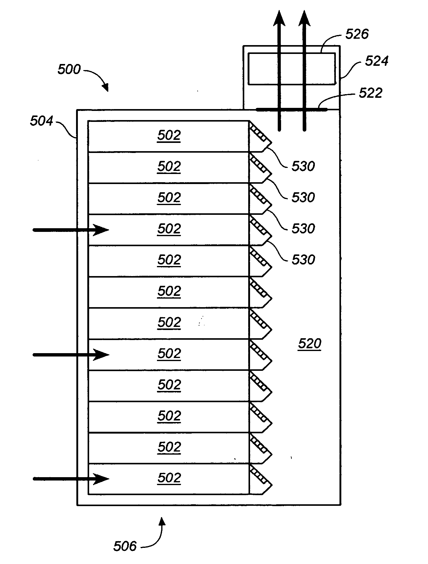
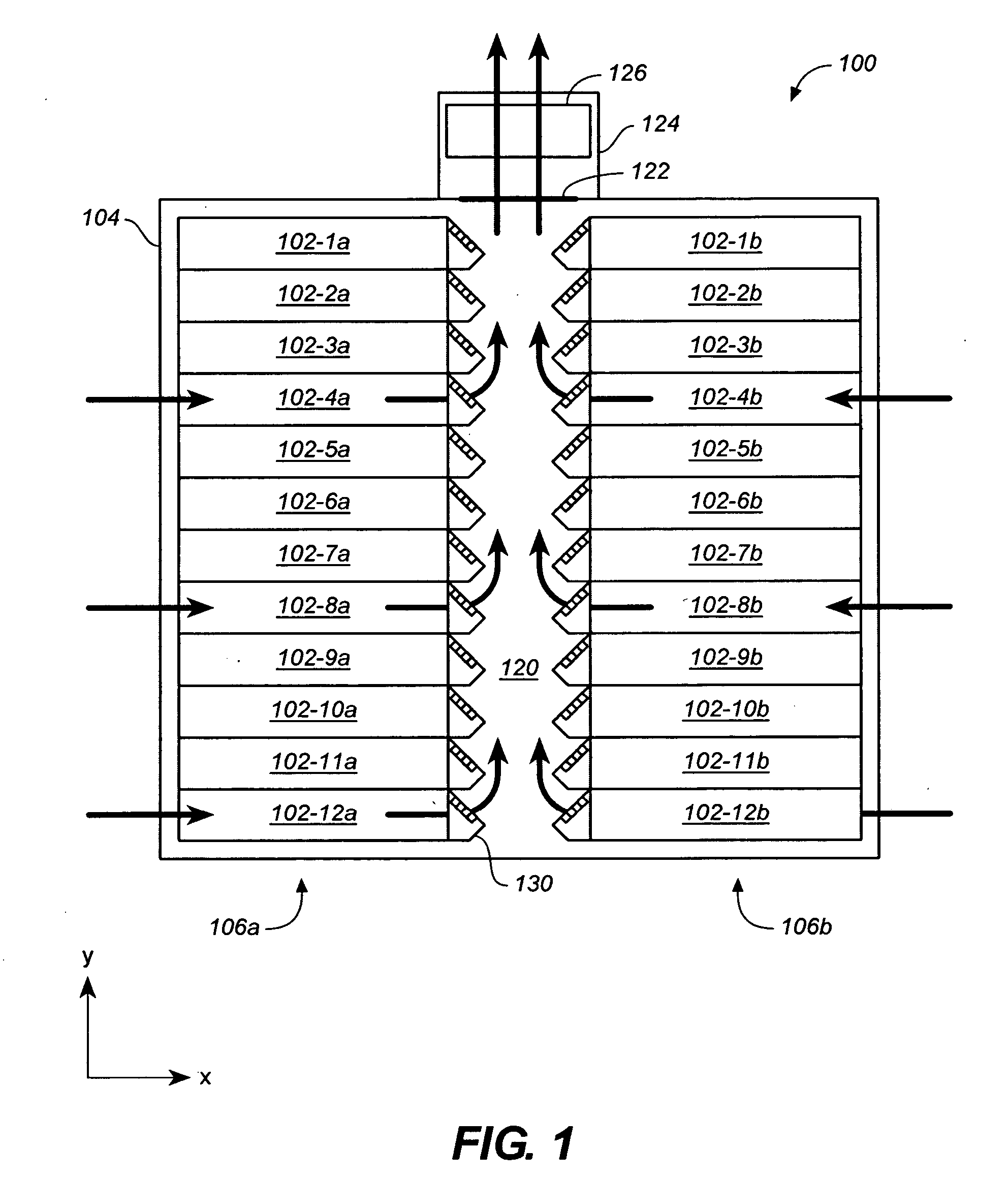
[0023]FIG. 1 shows a simplified cross-sectional side view of a rack-based computer system 100 comprising a rack assembly 104 having a plurality of computers 102 (i.e., 102-1a through 102-12a and 102-1b through 102-12b) supported therein, in accordance with embodiments of the present invention. In some embodiments, the rack assembly 104 may comprise a rack structure and a cabinet housing or enclosure surrounding the rack structure. Each of the ...


PUM


Abstract

A computer system having a fan assembly is provided. In one example, the computer system includes a computer chassis for mounting with a computer rack, the computer chassis comprising a front portion and a rear portion and including a main board. The computer system further includes a fan assembly positioned adjacent to a rear portion of the computer chassis, the fan assembly configured to draw air through the computer toward the rear portion of the computer chassis along a first direction and to expel the air in a second airflow direction non-parallel with the first direction.

Description

RELATED APPLICATION [0001] The present application claims the benefit of U.S. Provisional Patent Application Nos. 60 / 569,019, filed May 7, 2004 and entitled “DIRECTIONAL FAN ASSEMBLY”, 60 / 569,020, filed on May 7, 2004 and entitled “ELECTROMAGNETIC INTERFERENCE SHIELD FOR I / O PORTS”; 60 / 568,969, filed May 7, 2004 and entitled “INTERFACE ASSEMBLY”; and 60 / 569,025, filed May 7, 2004, entitled “RACK MOUNTED COMPUTER SYSTEM”; all of which are hereby incorporated by reference as if fully set forth herein.BACKGROUND [0002] 1. Field [0003] This is related generally to electronic equipment, such as computer systems for use in a rack-based computer system. Certain aspects relate to methods and systems for moving air within computer systems and rack based-computer systems. [0004] 2. Description of Related Art [0005] As information technology has rapidly progressed, computer network centers such as server farms and server clusters have become increasingly important to our society. The server fa...

Claims


Application Information

Patent Timeline
IPC IPC(8): G06F1/20H05K5/00H05K7/20
CPCH05K7/20736G06F1/20
Inventor COGLITORE, GIOVANNICASEBOLT, MATTHEW P.RANDALL, JACK E.GALLO, NIKOLAI S.
Owner HEWLETT-PACKARD ENTERPRISE DEV LP
Why Eureka
Try Eureka