

Speaker device
a technology of speaker device and speaker coil, which is applied in the direction of deaf-aid sets, transducer details, electrical transducers, etc., can solve the problem that the voice coil cannot be held at a predetermined stationary position within the device,
- Summary
- Abstract
- Description
- Claims
- Application Information
AI Technical Summary
Benefits of technology
Problems solved by technology
Method used
Image

Examples
first embodiment
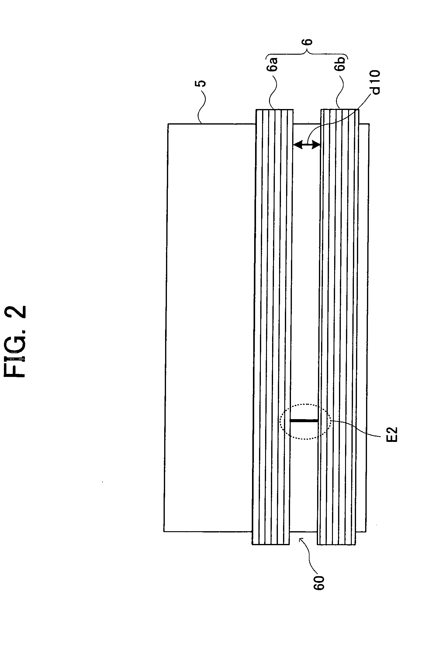
[0033] In a speaker device according to a first embodiment, a recess (concave) portion is formed between voice coils. Thereby, the above effect of the invention is obtained.
(Configuration of Speaker Device)
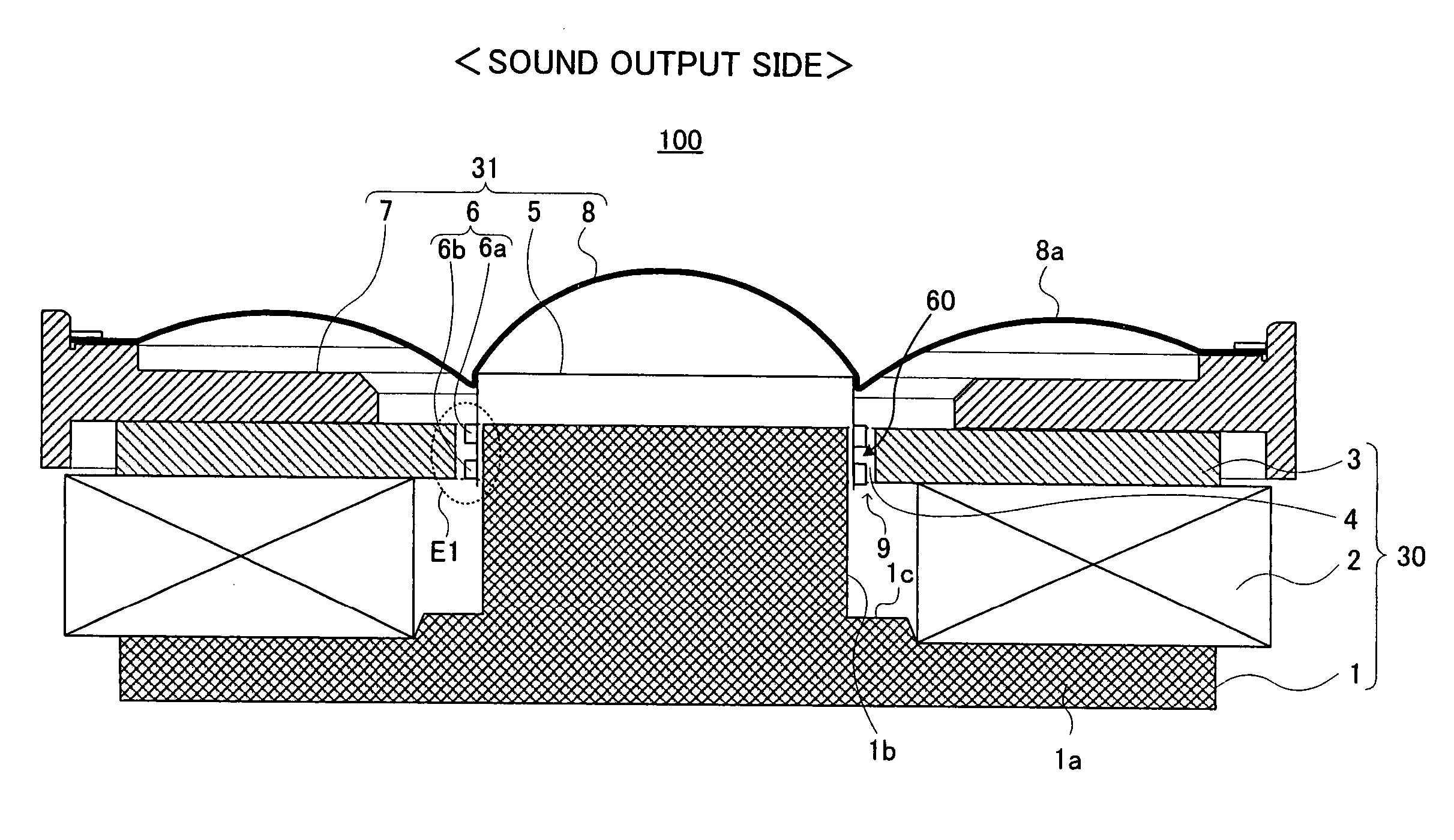
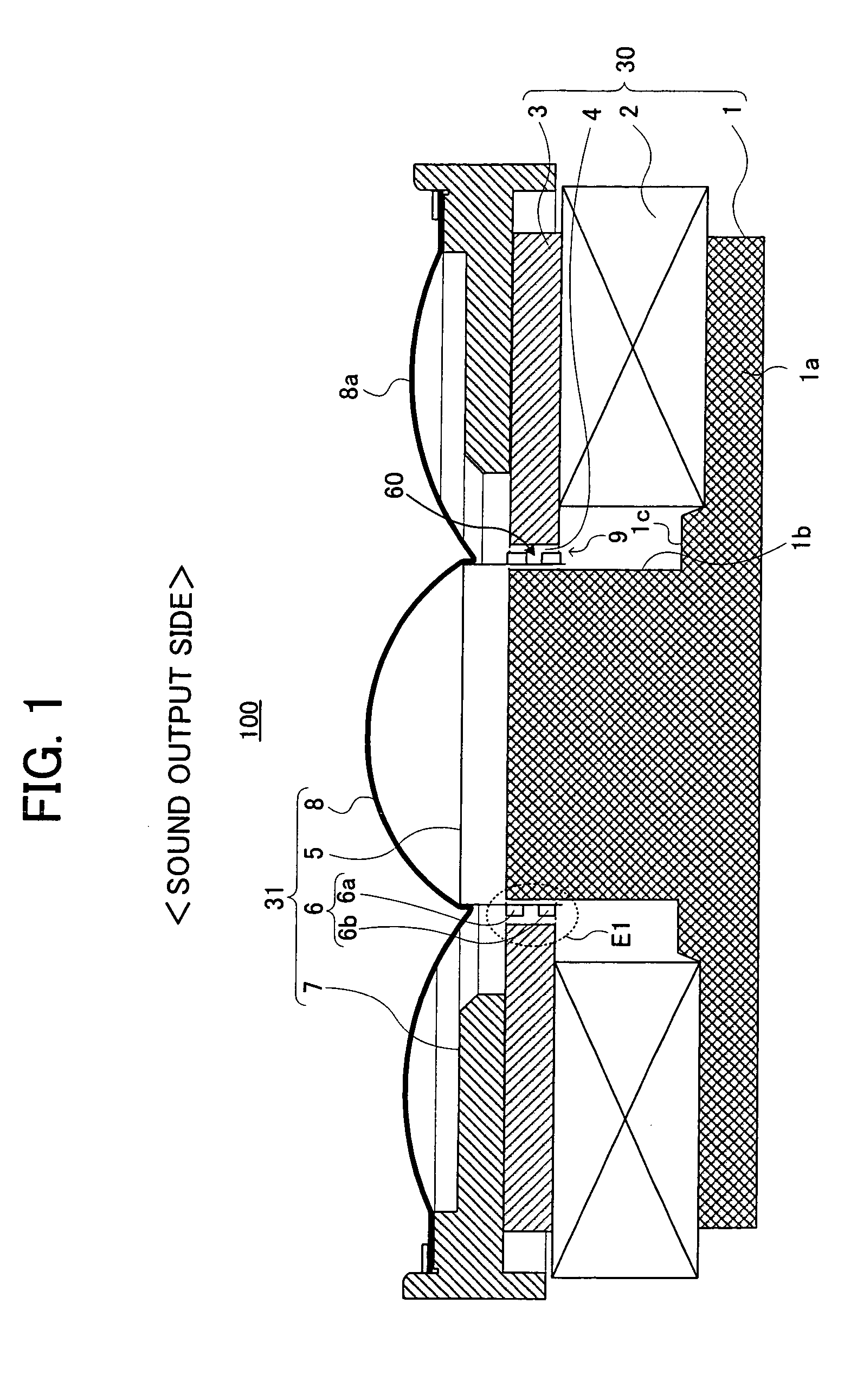
[0034] In FIG. 1, an outline configuration of a speaker 100 according to the first embodiment of the invention is schematically shown. FIG. 1 is a sectional view when the speaker device 100 is cut along a plane containing a central axis thereof. Referring to FIG. 1, the configuration of the speaker device 100 of the first embodiment will be described.
[0035] The speaker device 100 mainly includes a magnetic circuit system 30 having a pole piece 1, an annular magnet 2, an annular plate 3 and magnetic fluid 4, and a vibration system 31 having a voice coil bobbin 5, a voice coil 6, a frame 7 and a vibrating plate 8.
[0036] First, the respective constituent elements of the magnetic circuit system 30 will be described.
[0037] The pole piece 1 has substantially an inverted T section....
second embodiment
[0061] In a speaker device 200 according to a second embodiment, a recess portion is formed on a voice coil bobbin located within the winding width of a voice coil provided within a magnetic gap. Thereby, the same effect as that in the speaker device 100 according to the first embodiment is obtained.
[0062] Referring to FIGS. 5 and 6, a configuration of the speaker device 200 according to the second embodiment will be described. FIG. 5 schematically shows an outline configuration of the speaker 200 according to the second embodiment of the invention. FIG. 6 is a side view showing only the configuration of a voice coil 62 wound around a voice coil bobbin 5 in the speaker device 200. The speaker device 200 according to the second embodiment has basically the same configuration as that of the speaker device 100 according to the first embodiment, and the former and the latter are different only in the configuration of the voice coil and the voice coil bobbin. Accordingly, in the descrip...
third embodiment
[0068] In a speaker device 300 according to a third embodiment, as constituent elements of a vibration system 31, a first annular member and a second annular member having annular shapes are provided. Further, the former is located at the upper side of a voice coil 6 and mounted to a voice coil bobbin 5, and the latter is located at the lower side of the voice coil 6 and mounted to the voice coil bobbin 5. Thereby, a recess portion is formed by the first and second annular members and the outer circumferential wall of the voice coil 6 located between them. Thereby, the same effect as that of the speaker device 100 according to the first embodiment is obtained.
[0069] Referring to FIGS. 8 and 9, a configuration of the speaker device 300 according to the third embodiment will be described. FIG. 8 schematically shows an outline configuration of the speaker 300 according to the third embodiment of the invention. FIG. 9 is a side view showing only the configuration of a voice coil 62 wou...
PUM
 Abstract
Description
Claims
Application Information