
Low-mid turbine temperature abradable coating

a technology of abradable coating and turbine blades, which is applied in the direction of machines/engines, liquid fuel engines, mechanical equipment, etc., can solve the problems of reducing the efficiency of the turbine engine, unable to achieve the abradable coating that can be applied to the blades operating in the low to mid temperature turbine stage of the land-based turbine engine, and unable to achieve the effect of abradable coating

Inactive Publication Date: 2005-12-22
SOLAR TURBINES
View PDF6 Cites 11 Cited by
  • Summary
  • Abstract
  • Description
  • Claims
  • Application Information

AI Technical Summary

Problems solved by technology

Thus, at lower temperatures and loads, the clearance between the blades and the housings may be excessively large.
The large clearance will decrease the efficiency of the turbine engine by allowing the gases and / or compressed air to flow around the blades at lower temperatures and loads.
Although the abradable coatings have been able to increase turbine engine efficiency, an abradable coating that can be applied to turbine blades operating in low to mid temperature turbine stages of a land-based turbine engine has remained elusive.
For example, a low temperature stage of the turbine may be subjected to temperatures between 950-1300° F., a mid-temperature stage of the turbine may be subjected to temperatures between 1300-1500° F., and a high temperature stage of the turbine may be subjected to temperatures above 1500° F. Because at each stage, the turbine operates within a different temperature range, an abradable coating that works in one stage of the turbine may not provide the oxidation resistance and structural integrity required for a higher temperature stage.
However, it is still unknown what percentages of the matrix-forming component, the solid lubricant and the thermoplastic that can provide abradability while maintaining structural integrity and oxidation resistance at temperatures between 950-1500° F. for extended periods of time.
Although the agglomerates supposedly provide abradability, the high volume of the agglomerates likely negatively affect the lifetime and integrity of the coating.
Because stationary gas turbine engines often require an overhaul lifetime on the order of 30,000 hours, the Sulzer Metco abradable coating would not be durable in stationary gas turbine engines.

Method used


Image

  • Low-mid turbine temperature abradable coating
  • Low-mid turbine temperature abradable coating
  • Low-mid turbine temperature abradable coating

Examples


Embodiment Construction

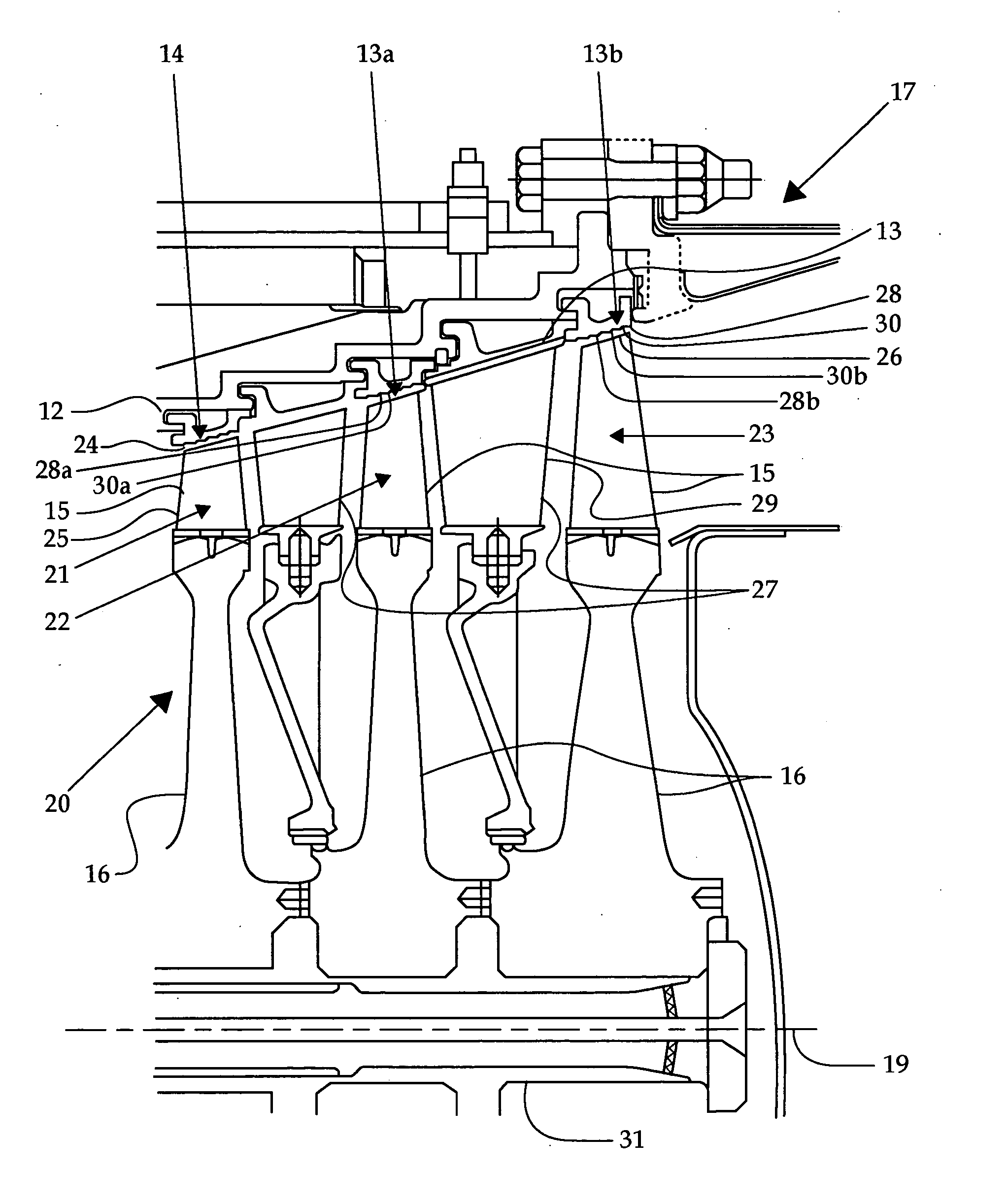
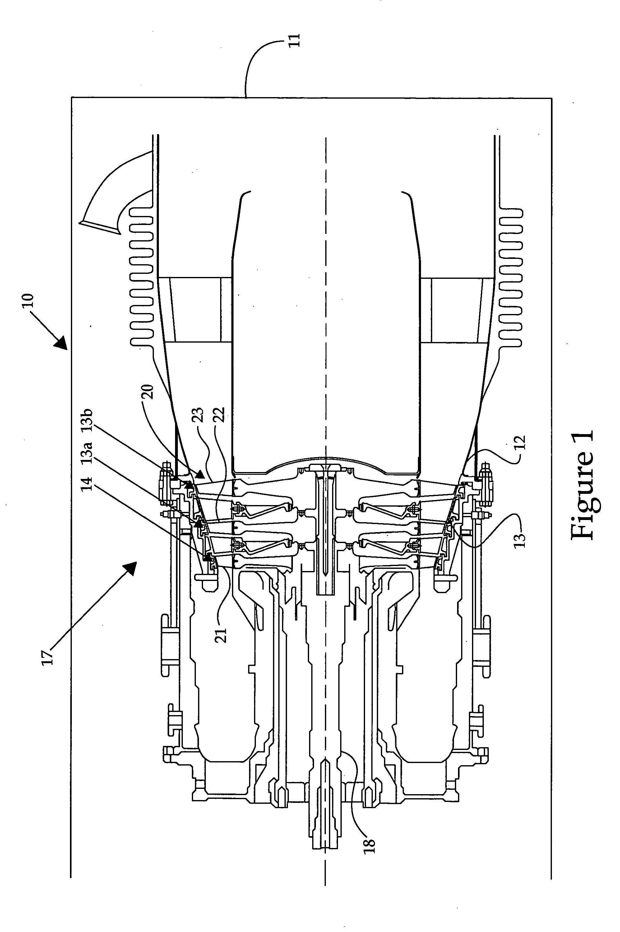
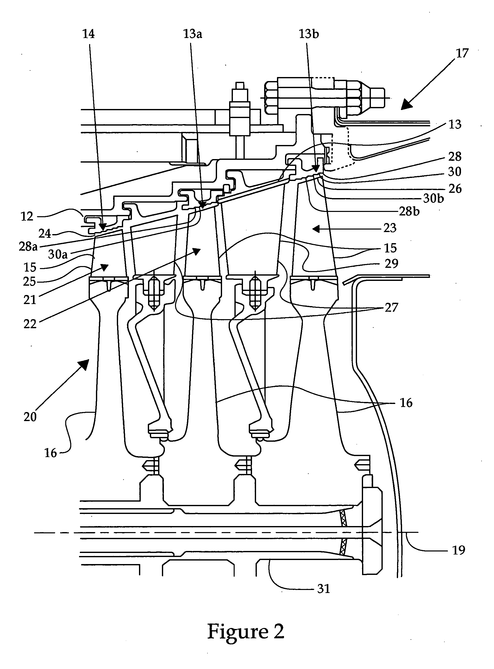
[0012] Referring to FIG. 1, there is shown a cross-sectioned view of a turbine engine 10, according to the present disclosure. The turbine engine 10, being an apparatus, is preferably a land-based gas turbine engine. The turbine engine 10 includes a compressor section (not shown) and a combustion section (not shown) both upstream from a turbine section 17. Ambient air is drawn into the compressor section of the turbine engine 10 where it is compressed. The compressed air is combined with fuel and burned in the combustion section. The high pressure and high temperature exhaust gases from the combustion drive a turbine 20 positioned within the turbine section 17 that is operably coupled to the compressor via a central shaft 18. The turbine engine 10 includes an engine housing 11 to which a turbine section housing 12, herein referred to as a shroud, is attached.

[0013] The turbine section housing 12 includes a plurality of temperature sections including a 950-1500° F. section 13. In th...


PUM

PropertyMeasurementUnit
Temperatureaaaaaaaaaa

Abstract

In order to minimize a clearance between a turbine and its housing, and thus, improve the efficiency of a turbine engine, an abradable coating can be applied to an inner surface of the turbine housing. However, there are no known abradable coatings that can be applied to a housing that is subjected to temperatures between 950-1500° F. for extended periods of time. The apparatus of the present disclosure includes a housing including a 950-1500° F. section in which at least one rotating blade row is positioned. The rotating blades and the 950-1500° F. section each includes a surface being comprised of a relatively non-abradable material. The surface of the housing comprised of the relatively non-abradable material is covered by a 950-1500° F. relatively abradable coating that includes a metallic matrix and at least one of a thermoplastic and dry lubricant. The metallic matrix is 55-85% of the coating by volume.

Description

TECHNICAL FIELD [0001] This disclosure relates generally to apparatuses including abradable coatings, and more specifically to abradable coatings subjected to temperatures between 950-1,500° F. BACKGROUND [0002] Gas turbine engines generally include a compressor section, a combustion section and a turbine section. A compressor within the compressor section and a turbine within the turbine section each can include a plurality of rotors attached to a central rotating shaft. The rotors include a plurality of blades that project radially therefrom. Both the compressor and turbine are encased in separate cylindrical housings, creating a clearance between the rotating blades and each housing. The clearance between the blades and the housings should be designed in order to assure that the blades, when rotating, do not make contact with the housings. Because the coefficient of expansion of the blades may differ from that of the housings, the clearance between the blades and the housing must...

Claims


Application Information

Patent Timeline
IPC IPC(8): C23C4/04C23C30/00F01D5/20F01D11/12
CPCC23C4/04F01D11/122C23C30/00
Inventor NAVA, IRENE L.COE, MICHAEL A.
Owner SOLAR TURBINES
Learn More