Fluid conditioning system

a conditioning system and fluid technology, applied in the field of medical cutting, irrigating, evacuating, cleaning, drilling techniques, etc., can solve the problems of atomized particles exploding and imparting disruptive cutting forces onto the tissu

Inactive Publication Date: 2005-12-22
BIOLASE TECH INC
View PDF72 Cites 18 Cited by
  • Summary
  • Abstract
  • Description
  • Claims
  • Application Information

AI Technical Summary

Benefits of technology

[0014] The fluid conditioning system of the present invention is adaptable to most existing medical and dental cutting, irrigating, evacuating, cleaning, and drilling apparatuses. Flavored fluid is used in place of regular tap water or other types of water such as distilled, deionized, sterile, or water with a controlled number of colony forming units (CFU) per milliliter, etc., during drilling operations. In the case of a laser surgical operation, electromagnetic energy is focused in a direction of the tissue to be cut, and a fluid router routes flavored fluid in the same direction. The flavored fluid may appeal to the taste buds of the patient undergoing the surgical procedure, and may include any of a variety of flavors, such as a fruit flavor or a mint flavor. In the case of a mist or air spray, scented air may be used to mask the smell of burnt or drilled tissue. The scent may function as an air freshener, even for operations outside of dental applications.

Problems solved by technology

In certain implementations, absorption of the electromagnetic energy by the atomized particles causes the atomized particles to explode and impart disruptive cutting forces onto the tissue.

Method used


Image

  • Fluid conditioning system
  • Fluid conditioning system
  • Fluid conditioning system

Examples


Embodiment Construction

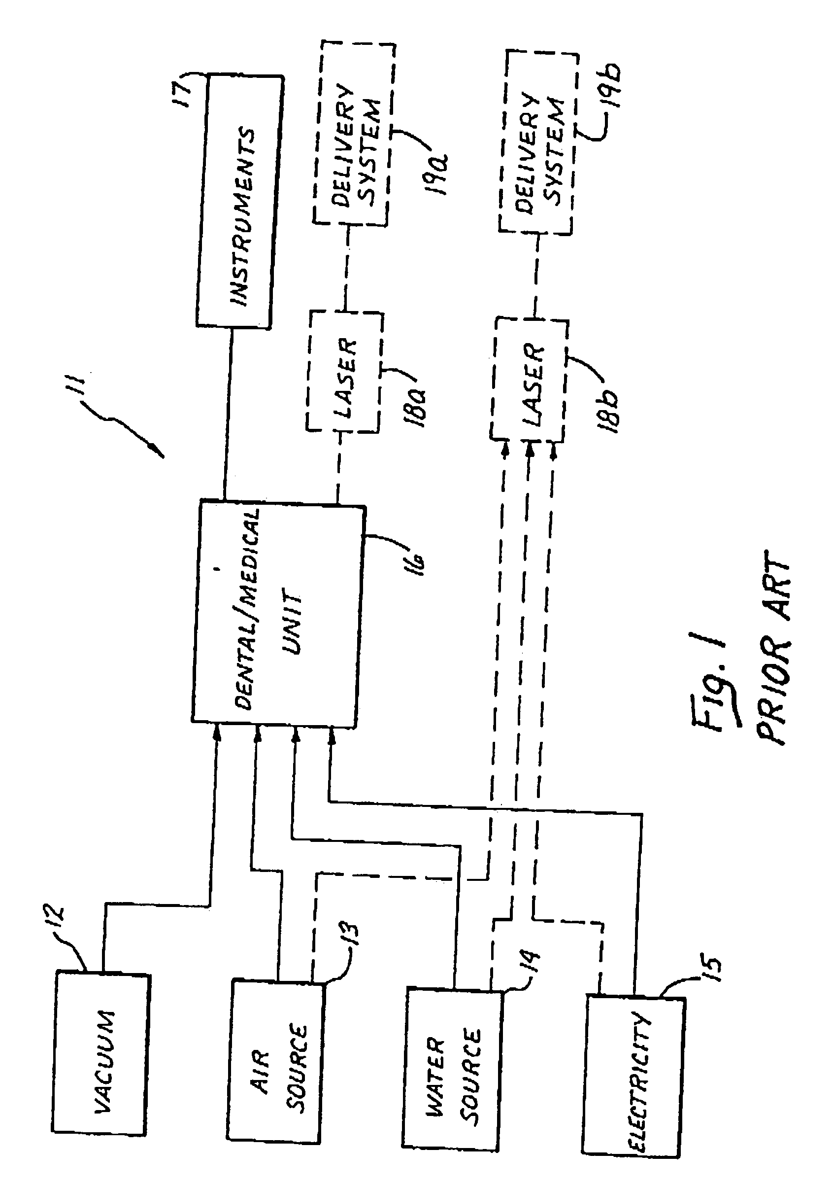
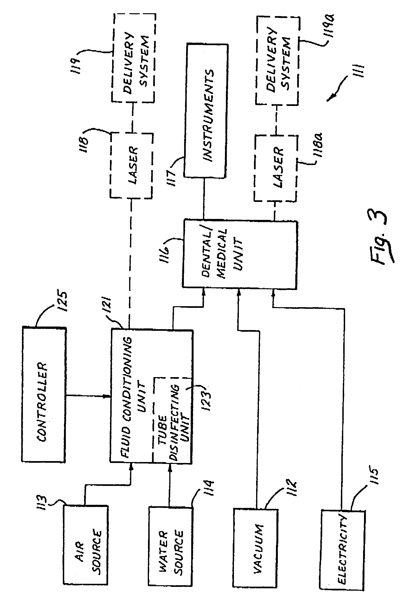
[0047] A dental / medical work station 111 of the present invention is shown in FIG. 3, with elements similar to those shown in FIG. 1 proceeded by a “1”. The dental / medical work station 111 comprises a conventional air line 113 and a conventional water line 114 for supplying air and water, respectively. As used herein, the term “water” is intended to encompass various modified embodiments of liquids such as distilled water, deionized water, sterile water, tap water or water that has a controlled number of colony forming units (CFU) for the bacterial count, etc. For instance, drinking water is often chemically treated to a level where there are no more than 500 CFU / ml and in some cases between 100-200 CFU / ml. A vacuum line 112 and an electrical outlet 115 supply negative air pressure and electricity to the dental / medical (e.g., dental or medical) unit 116, similarly to the vacuum 12 and electrical 15 lines shown in FIG. 1. The fluid conditioning unit 121 may, alternatively, be placed ...


PUM


Abstract

A fluid conditioning system is adapted to condition the fluid used in medical and dental cutting, irrigating, evacuating, cleaning, and drilling operations. The fluid may be conditioned by adding flavors, antiseptics and/or tooth whitening agents such as peroxide, medications, and pigments. In addition to the direct benefits obtained from introduction of these agents, the laser cutting properties may be varied from the selective introduction of the various agents.

Description

CROSS-REFERENCE TO RELATED APPLICATIONS [0001] This application claims the benefit of U.S. Provisional Application No. 60 / 535,110, filed Jan. 8, 2004 and entitled FLUID CONDITIONING SYSTEM, the contents of which are expressly incorporated herein by reference. This application is also a continuation-in-part of U.S. application Ser. No. 10 / 435,325, filed May 9, 2003, which is a divisional of U.S. application Ser. No. 09 / 997,550, filed Nov. 27, 2001, issued as U.S. Pat. No. 6,561,803, which is a continuation of U.S. application Ser. No. 09 / 256,697, filed Feb. 24, 1999, issued as U.S. Pat. No. 6,350,123, which is a continuation-in-part of U.S. application Ser. No. 08 / 985,513, filed Dec. 5, 1997, now abandoned, which is a continuation of U.S. application Ser. No. 08 / 522,503, filed Aug. 31, 1995, issued as U.S. Pat. No. 5,741,247, the contents of all which are expressly incorporated herein by reference.BACKGROUND OF THE INVENTION [0002] 1. Field of the Invention [0003] The present inventi...

Claims


Application Information

Patent Timeline
Patent Type & Authority Applications(United States)
IPC IPC(8): A61C1/00A61H21/00A61K33/00A61K33/40
CPCA61K33/40A61C1/0061
Inventor RIZOIU, IOANA M.JONES, JEFFREY W.
Owner BIOLASE TECH INC
Why Eureka
Try Eureka