Slit valves bridging between the tip and distal side wall of catheter tubes and methods

Inactive Publication Date: 2005-12-22
NORDGREN CORP
View PDF7 Cites 73 Cited by
  • Summary
  • Abstract
  • Description
  • Claims
  • Application Information

AI Technical Summary

Benefits of technology

[0008] A further dominate object is the provision of slit valves in the distal tips of catheter tubes so as to extend somewhat into the adjacent side wall of the catheter tube by which occlusion and interference problems are greatly reduced, if not eliminated.

Problems solved by technology

Also, interference can occur between the indwelling lips forming a slit, as they are flexed outwardly, and the wall of the body cavity in which the catheter tube and slit valve are disposed, which either prevents the slit valve from opening or undesirably limits the extent to which it is permitted to open.

Method used


Image

  • Slit valves bridging between the tip and distal side wall of catheter tubes and methods
  • Slit valves bridging between the tip and distal side wall of catheter tubes and methods
  • Slit valves bridging between the tip and distal side wall of catheter tubes and methods

Examples


Embodiment Construction

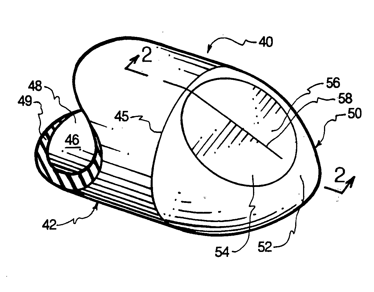
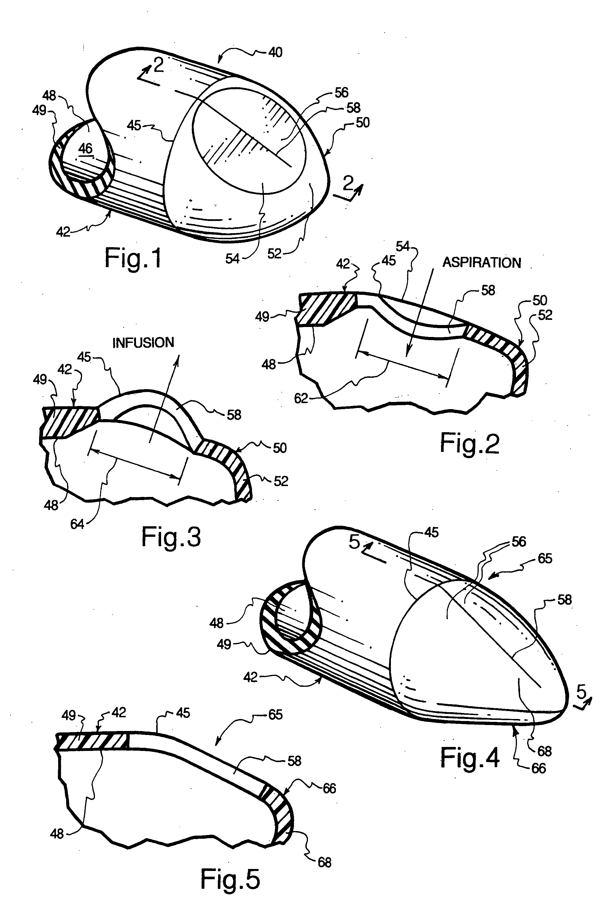
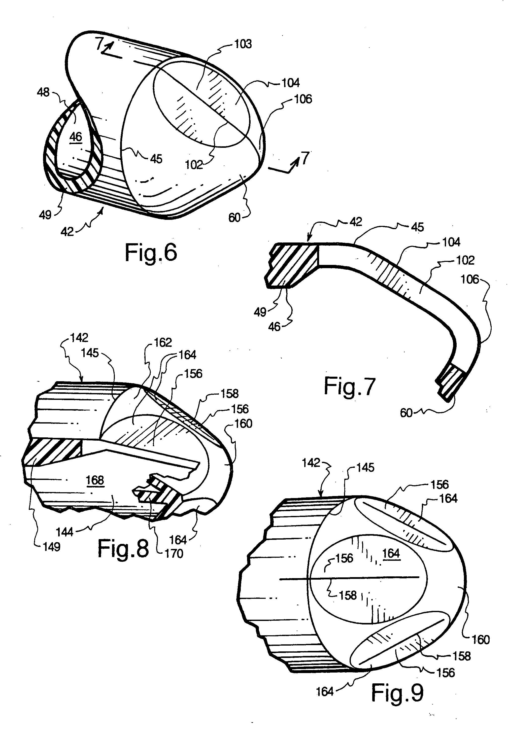
[0020] The present invention solves or reduces past problems in the catheter-related slit valve field, applicable to the human respiratory system, the human circulatory system, and other body cavities. Apart from whether a catheter tube comprises a sidewall slit valve or does not, one or more slit valves, which may be in a variety of forms, are disposed in an otherwise normally closed distal end of each catheter tube so as to extend somewhat into the wall of the catheter tube at the distal end thereof, whereby passageway occlusion problems and body cavity interference problems are greatly reduced, if not eliminated and the degree of flexure to open inwardly for aspiration is less than to open outwardly for infusion. In some embodiments a tip slit valve may traverse an apex of the tip.

[0021] Accordingly, the tip and the side wall at the distal end of a single or multiple lumen catheter tube may comprise one or more slit valves to both aspirate and infuse. One or more slit valves may...


PUM


Abstract

Slit valves are disclosed which are placed in normally closed distal catheter tips so as to extend somewhat into the wall at the distal ends of catheter tubes whereby different rates of flow through the slit valves are achieved for aspiration and infusion, respectively.

Description

CONTINUITY [0001] This application is a continuation-in-part of my co-pending U.S. patent application Ser. No. 10 / 647,039, filed Aug. 21, 2003, which is a continuation of Ser. No. 09 / 542,503, filed Apr. 3, 2000.FIELD OF INVENTION [0002] The present invention relates generally to slit valves for catheters and, more particularly to a variety of configurations of slit valves disposed in otherwise closed catheter tips so as to also extend into the adjacent side wall of catheter tubes at the distal end thereof, and related methods. BACKGROUND [0003] In the past, slit valves have traditionally been used only in the side walls of otherwise closed catheter tubes to infuse or aspirate fluid. Use of such side wall slit valves has been directed to infusion and aspiration of liquids in the cardiovascular systems of medical patients, infusion and aspiration of fluids in the respiratory systems of medical patients, and infusion and aspiration in other body cavities. [0004] Disadvantageously, when...

Claims


Application Information

Patent Timeline
Patent Type & Authority Applications(United States)
IPC IPC(8): A61M5/00A61M25/00
CPCA61M25/0075
Inventor NORDGREN, GREG
Owner NORDGREN CORP
Why Eureka
Try Eureka