Re-positionable vehicle control-by-wire assembly, method, and system

a vehicle control and wire technology, applied in the direction of underwater vessels, braking components, non-deflectable wheel steering, etc., can solve the problems of major positional adjustment of the control system, inability to provide the resistance of the vehicle driver at the input assembly, and inability to adjust the major position of the control system

Active Publication Date: 2005-12-22
FCA US
View PDF7 Cites 54 Cited by
  • Summary
  • Abstract
  • Description
  • Claims
  • Application Information

AI Technical Summary

Benefits of technology

[0006] A first aspect of the present invention provides a vehicle control assembly. The assembly includes a controller. A steer-by-wire component, a brake-by-wire component, and an ac...

Problems solved by technology

As the control-by-wire systems typically lack mechanical linkages, resistance provided to a vehicle driver at the input assembly may also be lacking.
The often complex mechanical linkages may compri...

Method used


Image

  • Re-positionable vehicle control-by-wire assembly, method, and system
  • Re-positionable vehicle control-by-wire assembly, method, and system
  • Re-positionable vehicle control-by-wire assembly, method, and system

Examples


Embodiment Construction

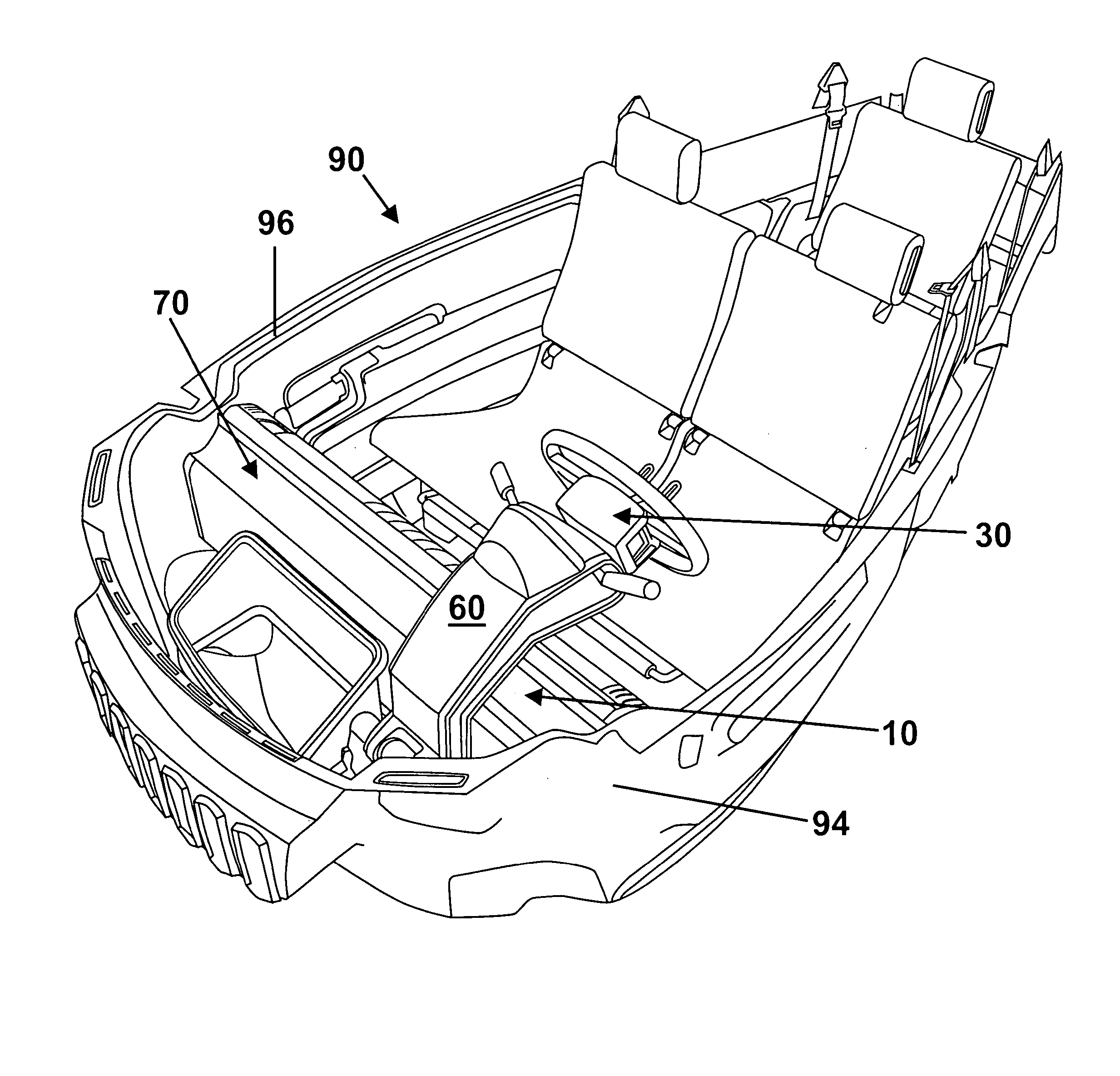
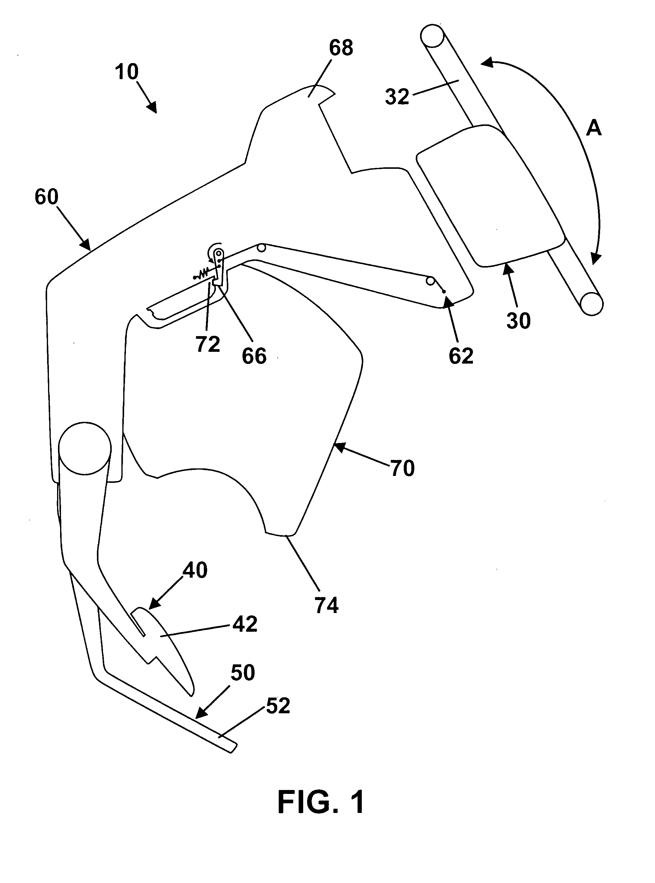
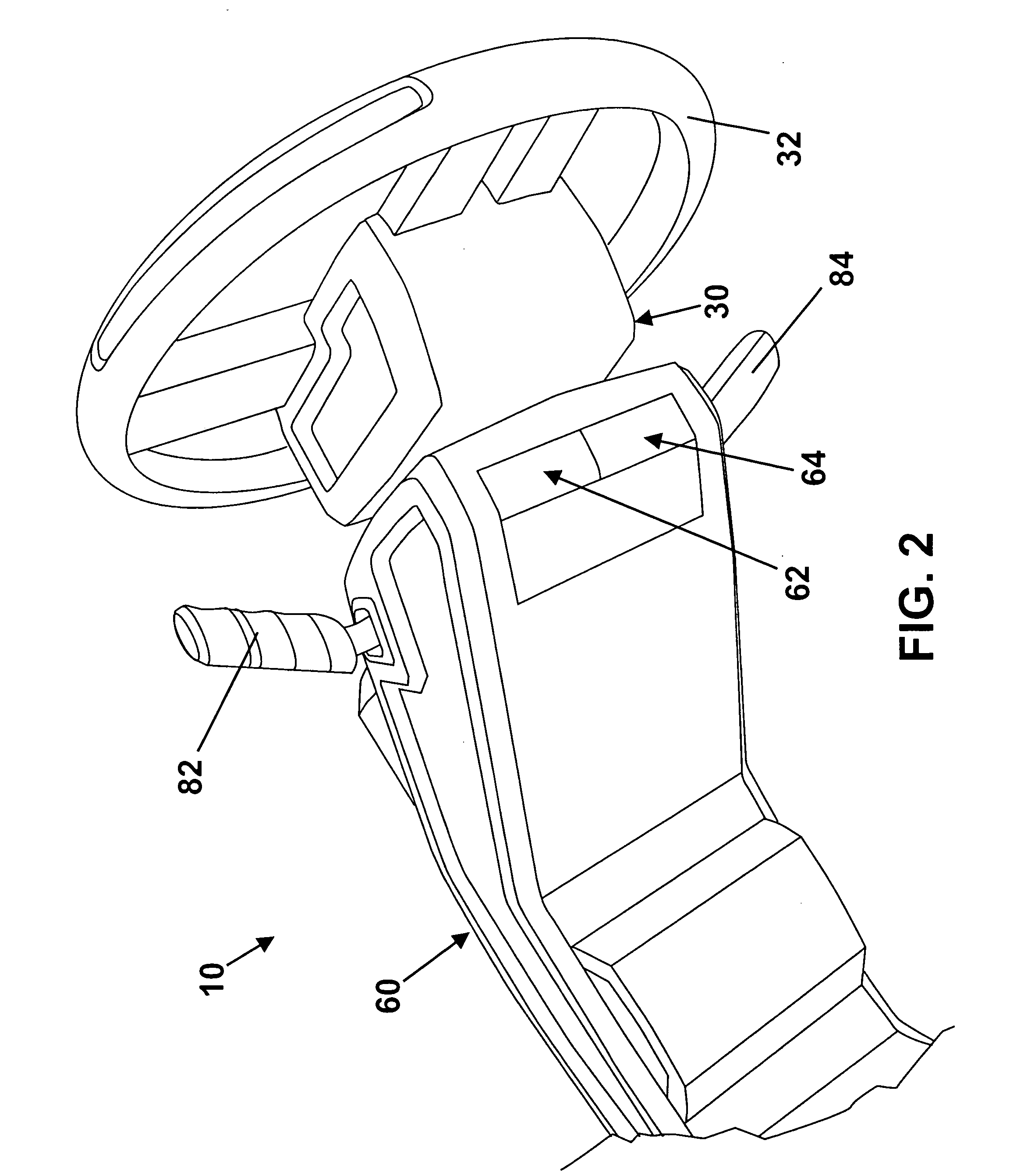
[0015] Referring to the drawings, wherein like reference numerals refer to like elements, FIGS. 1-7 are alternative views of various portions of a vehicle control assembly in accordance with one embodiment of the present invention. The assembly is shown generally by numeral 10. Assembly 10 includes a steer-by-wire component 30, a brake-by-wire component 40, and an accelerator-by-wire component 50, each operably attached to a controller 60. Assembly 10 further includes a track 70 operably attached to a vehicle 90 wherein the controller 60 is laterally re-positionable with respect to the track 70. Those skilled in the art will recognize that the vehicle control assembly may vary and is not limited the description and illustrations provided herein. As used herein, the term “lateral” when referring to the re-positioning and / or movement of the controller 60 with respect to the track 70 is not limited to a strict linear side-to-side movement but to a generalized sideways movement follow...


PUM


Abstract

A vehicle control assembly and a method and system for controlling a vehicle. The assembly includes a controller. A steer-by-wire component, a brake-by-wire component, and an accelerator-by-wire component are each operably attached to the controller. A track is operably attached to the vehicle. The controller is laterally re-positionable with respect to the track. The method includes the steps of providing a controller, and steering, braking, and accelerating the vehicle by-wire with the controller. The method further includes the step of re-positioning the controller between a first vehicle side to a second vehicle side. The system includes controller means, and means for steering, braking, and accelerating the vehicle by-wire with the controller means. The system further includes means for reversibly positioning the controller means from a first vehicle side to a second vehicle side.

Description

TECHNICAL FIELD OF THE INVENTION [0001] The present invention relates generally to vehicular control systems. More particularly, the invention relates to a re-positionable vehicle control-by-wire assembly, method, and system. BACKGROUND OF THE INVENTION [0002] Conventional vehicle control systems (e.g., steering, brake, accelerator, etc.) typically include an input assembly (e.g., steering wheel, brake pedal, accelerator pedal, etc.) coupled to one or more actuators by a mechanical linkage (e.g., rods, hydraulic lines, gears, etc.). Control-by-wire systems may be used to replace the mechanical linkages and other components of the conventional control systems. Numerous control-by-wire systems are known in the art. Such systems provide several advantages over the conventional control systems including a reduction of parts and, in many instances, enhanced reliability and performance. As the control-by-wire systems typically lack mechanical linkages, resistance provided to a vehicle dri...

Claims


Application Information

Patent Timeline
IPC IPC(8): B62D1/18B63H21/22B63H25/02G06F17/00
CPCB60K2350/407B60T2260/02B60T2270/82B63H2025/022B63H21/21B63H21/22B63H25/02B62D1/18B60K2370/685
Inventor HOWELL, GREGORYLIM, STEPHEN T.MACEY, STUART P.
Owner FCA US
Why Eureka
Try Eureka