Knife having automatically loading blade

Inactive Publication Date: 2005-12-29
HUANG YIN HAN
View PDF7 Cites 32 Cited by
  • Summary
  • Abstract
  • Description
  • Claims
  • Application Information

AI Technical Summary

Benefits of technology

[0018] The other objective of the present invention is to provide a utility knife including an actuator devi

Problems solved by technology

However, after the knife blades have been worn out or damaged, it is required to separate the two housing members away from each other, for allowing the knife blades to be replaced with the other ones.
In these kinds of utility knives, the knife blades may not be easily and quickly replaced with the other ones without disengaging or disassembling the two housing members away from each other, such that the knife blades may not be easily and quickly replaced with the other new ones.
However, it will be difficult to engage a new knife blade into the blade support and the housing.
However, after the knife blades have been worn out or damaged, it is also required to separate the two housing members away from each other, or to rotate or move the casing away from the housing, to remove the spare blades from the

Method used


Image

  • Knife having automatically loading blade
  • Knife having automatically loading blade
  • Knife having automatically loading blade

Examples


Embodiment Construction

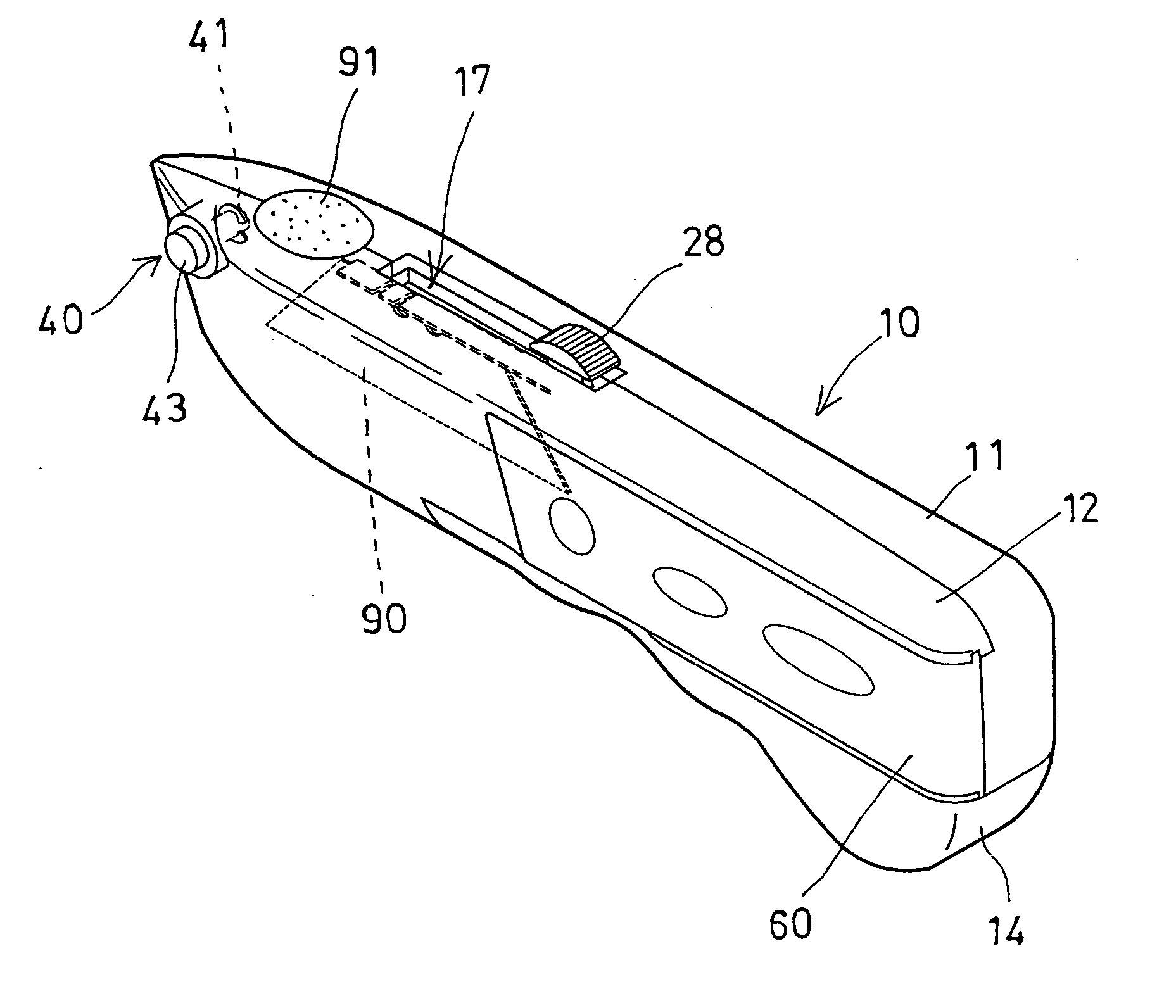
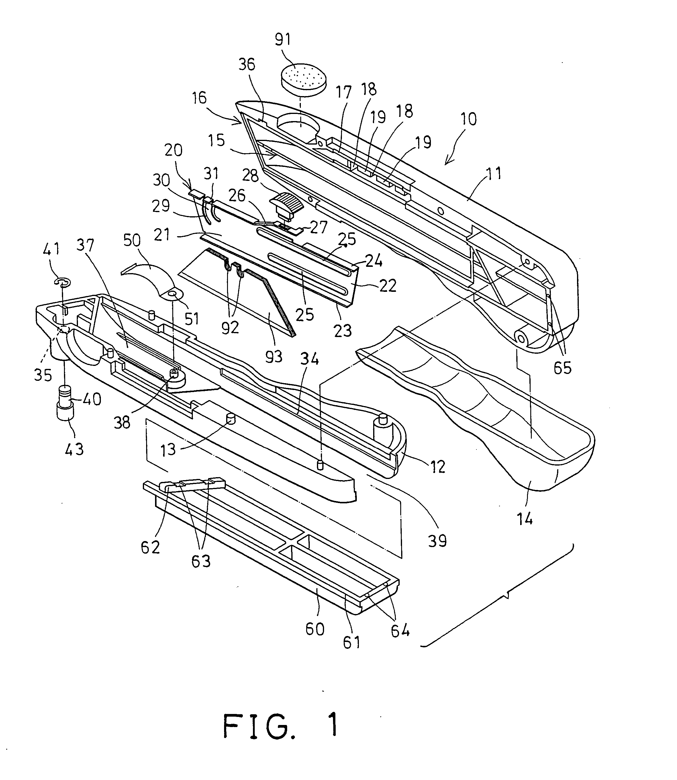
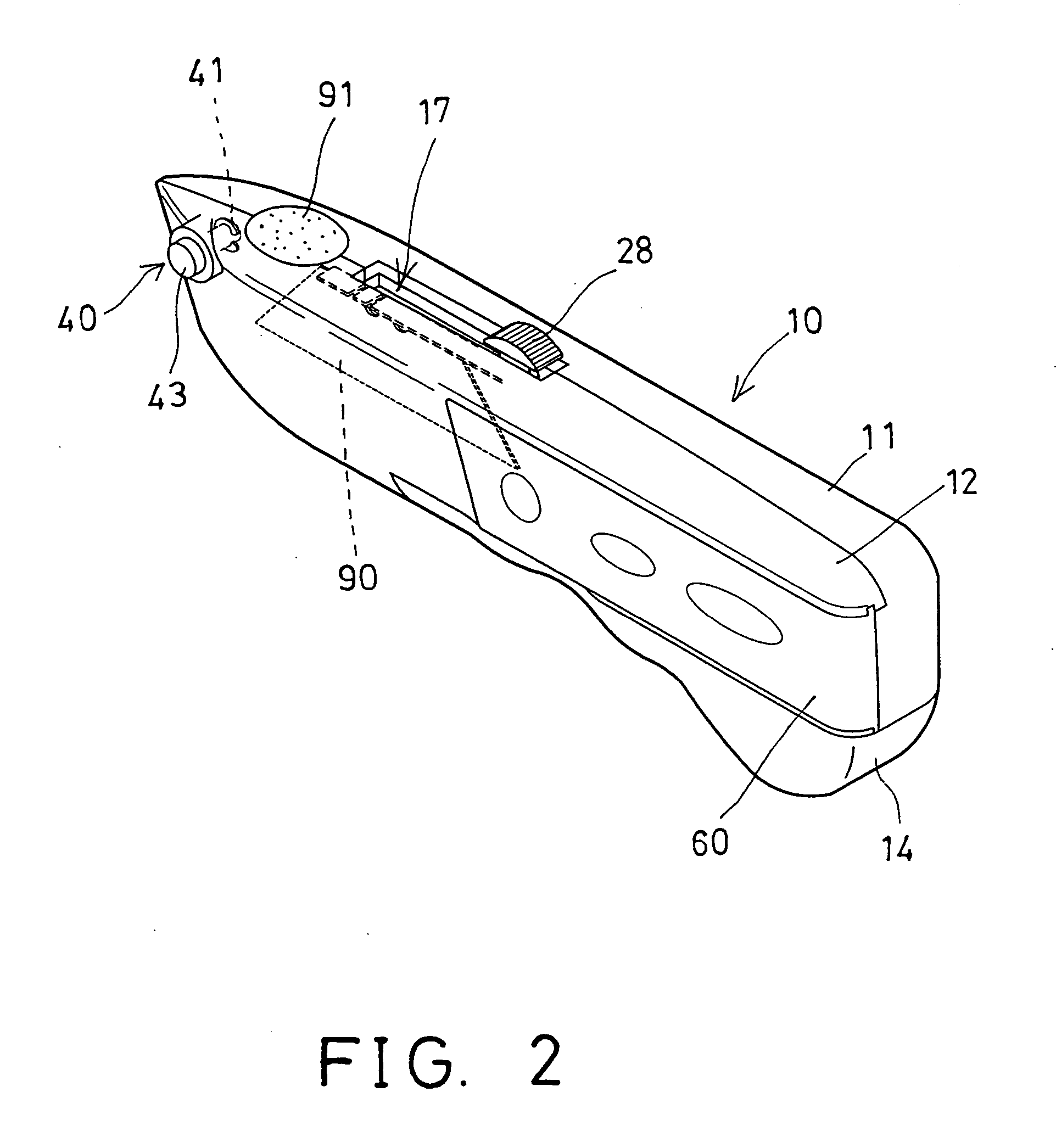
[0043] Referring to the drawings, and initially to FIGS. 1-4, a utility knife in accordance with the present invention comprises a handle 10 including such as two handle members 11, 12 secured together by adhesive materials, fasteners (not shown), or by welding processes. For example, one of the handle members 12 may include one or more juts 13 extended therefrom, and engaged into the other handle member 11, before the handle members 11, 12 are welded or secured together, for allowing the handle members 11, 12 to be solidly secured together.

[0044] The handle 10 includes a conventional passage 15 formed therein and having an open front 16 formed therein, for allowing a knife blade 90 to be slidably extended out through the open front 16 of the handle 10 to an outwardly extending working position (FIGS. 4, 9). A soft covering 14 may be attached to the lower portion of the handle 10, to allow the users to comfortably hold or grasp the handle 10. A pad 91 may be disposed in the front a...


PUM


Abstract

A utility knife includes a handle having a passage to slidably receive a blade carrier which has a space to receive a knife blade and to move the knife blade into or out of the handle. The blade carrier includes a spring limb having a latch to engage with and to anchor the knife blade to the blade carrier. An actuator device may selectively disengage the latch of the spring limb from the knife blade, to release the knife blade from the blade carrier. One or more spare blades may be received in the handle, and one spare blade may be biased into the space of the blade carrier when the blade carrier is moved into the handle and when the space of the blade carrier is emptied.

Description

BACKGROUND OF THE INVENTION [0001] 1. Field of the Invention [0002] The present invention relates to a utility knife, and more particularly to a utility knife having a knife blade loading structure to load the knife blades automatically. [0003] 2. Description of the Prior Art [0004] Various kinds of typical utility knives have been developed and comprise a blade carrier slidably received in a handle or a housing, to carry a knife blade, and to move the knife blade into and out of the housing between an outwardly working position and an inwardly receiving or storing position. [0005] For example, U.S. Pat. No. 6,163,963 to Huang, and U.S. Pat. No. 6,243,953 to Huang disclose two of the typical utility knives each also comprising a blade carrier slidably received in a housing to carry and to move the knife blade into and out of the housing. [0006] Normally, the typical utility knives comprise two housing members secured together, before the blade carrier slidably engaged into and recei...

Claims


Application Information

Patent Timeline
IPC IPC(8): B26B1/00B26B5/00
CPCB26B5/001
Inventor HUANG, YIN HAN
Owner HUANG YIN HAN
Why Eureka
Try Eureka