Panel section for sound barrier

a panel section and sound barrier technology, applied in the direction of sound producing devices, building components, instruments, etc., can solve the problems of affecting the transmission of light and the view of persons in the vicinity, the cost of suitable glass, to wit, of sufficient strength to serve such purposes, and the inability to manufacture and erect. the effect of cos

Inactive Publication Date: 2005-12-29
ARMTEC
View PDF7 Cites 13 Cited by
  • Summary
  • Abstract
  • Description
  • Claims
  • Application Information

AI Technical Summary

Benefits of technology

[0006] It is an object of the present invention to provide a transparent or translucent wall panel section for acoustical attenuation of a sound source that is relatively inexpensive to manufacture and erect.

Problems solved by technology

However, its wall panels, being cementitious, are completely opaque, and thereby block the transmission of light and the view of persons in the vicinity, which in certain circumstances can be undesirable, inter alia, from the standpoints of aesthetics and safety.
However, the cost of suitable glass, to wit, of sufficient strength to serve such purpose, is relatively high.
Further, glass suffers from a propensity to shatter into sharp shards upon impact, thereby rendering it difficult and dangerous to work with, and unsuitable for use in situations wherein impacts could be expected, such as, for example, alongside highways.
However, not only is the cost of such materials relatively high, but, by virtue, inter alia, of the thermal expansion properties of available synthetic materials, it can be difficult to secure panels constructed therefrom to suitable supports.
Moreover, supports that are constructed to accommodate panel movement during thermal expansion and contraction tend to increase the risk of withdrawal of the panels from their supports when the panels bow under wind or other loading; stiffening the panels against bowing by increasing their thickness adds detrimentally to cost and can impair light transmission, and similarly, increasing the size and complexity of the supports adds detrimentally to cost and can detract from the aesthetics of the wall.
For reasons such as these, the use of transparent or translucent sheets of synthetic materials as wall panel components in sound barriers has been limited.

Method used


Image

  • Panel section for sound barrier
  • Panel section for sound barrier
  • Panel section for sound barrier

Examples


Embodiment Construction

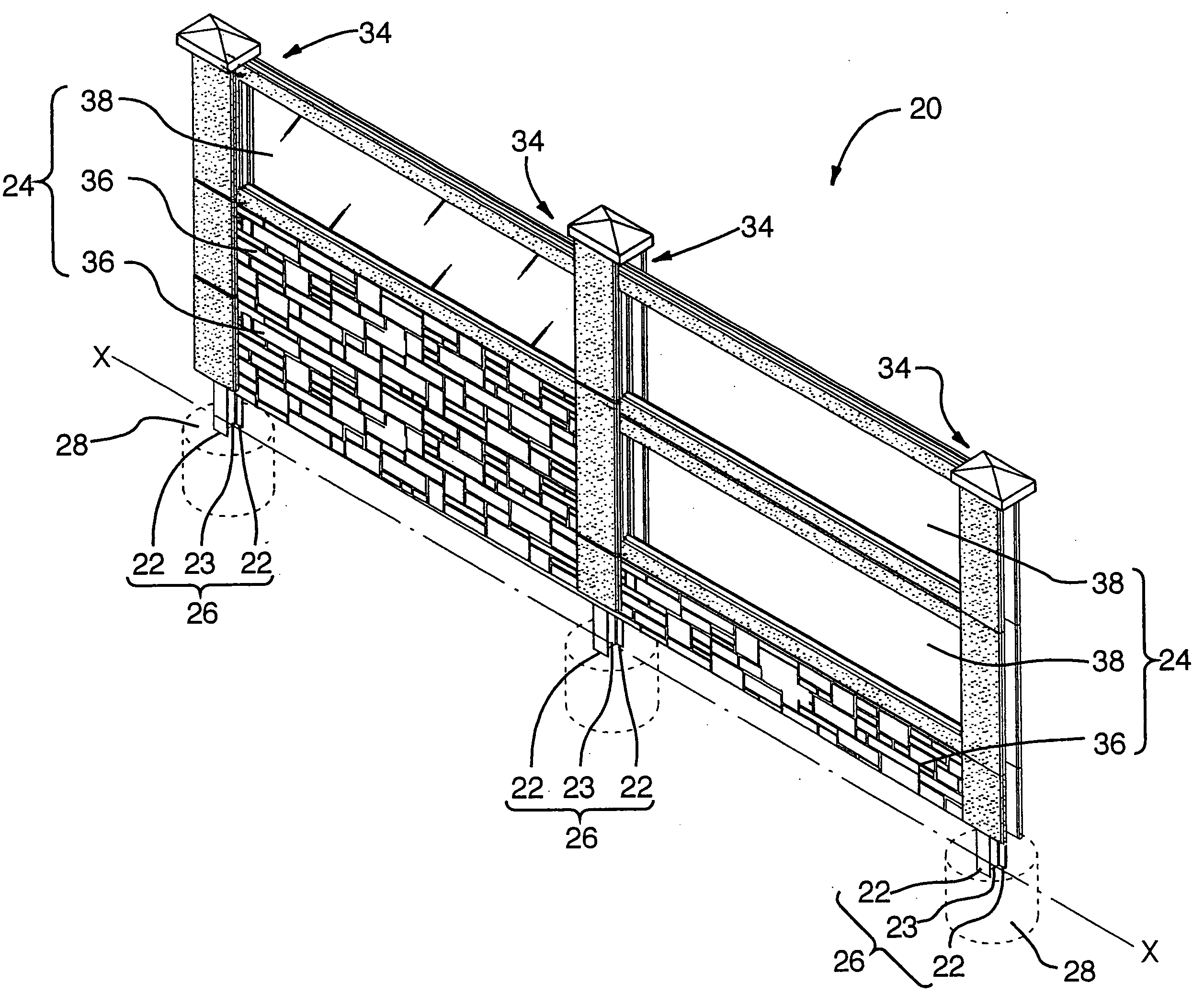
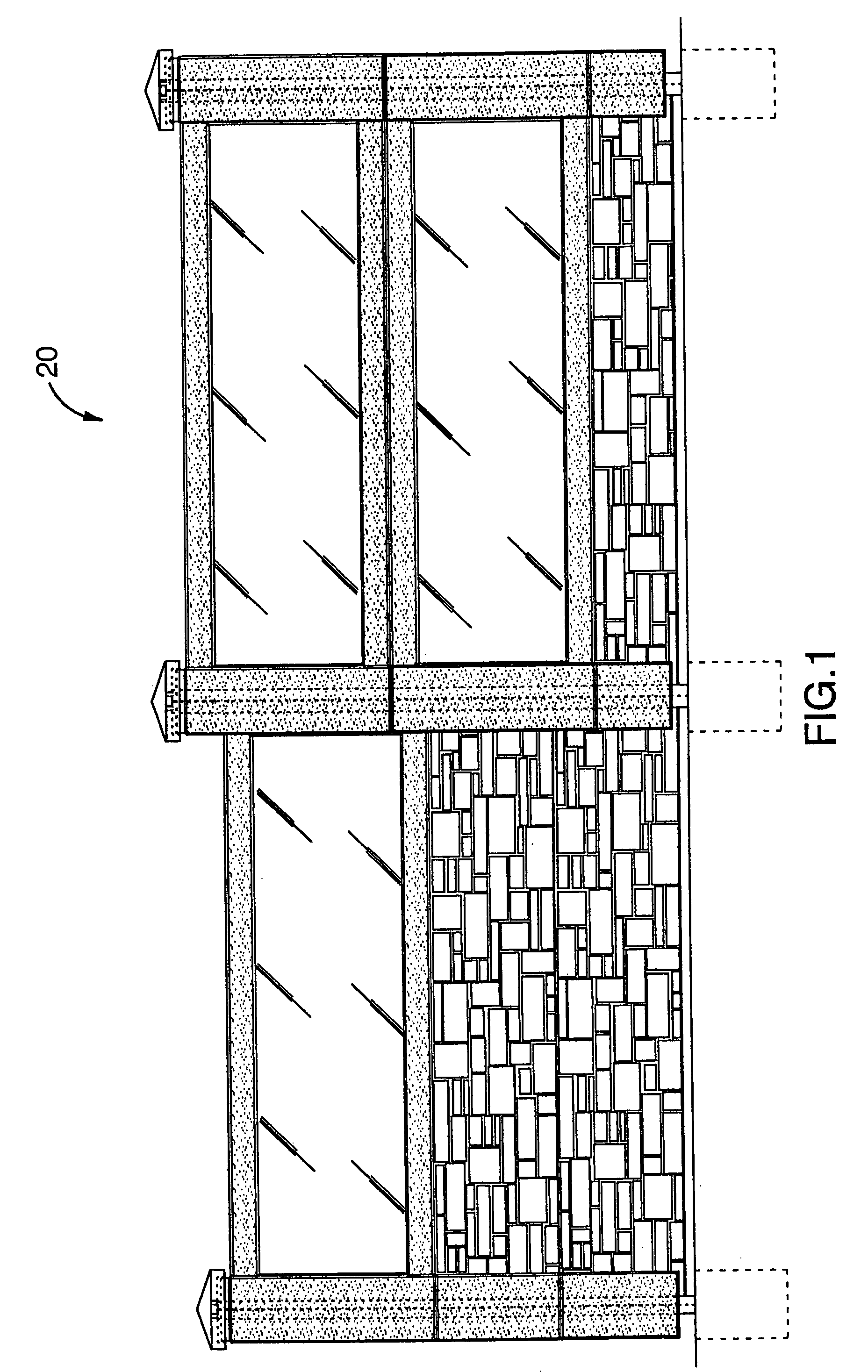
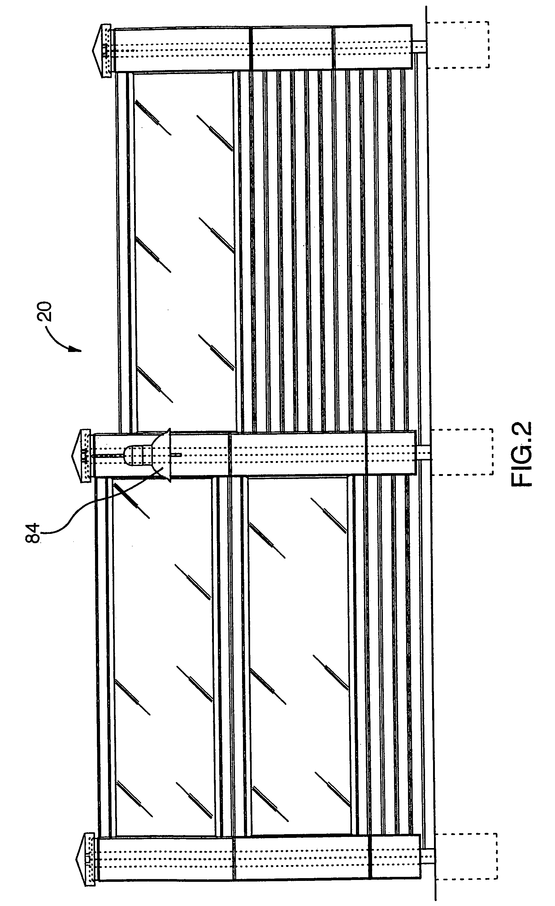
[0029] Referring to FIGS. 1 and 2, an improved sound barrier for acoustical attenuation of a sound source (not shown) and according to a preferred embodiment of the present invention is illustrated and designated with general reference numeral 20.

[0030] With general reference to FIG. 3, the improved sound barrier 20 of the preferred embodiment illustrated comprises at least two vertically-extending, ground-mounted steel I-beam columns 26 (three columns 26 are shown) and a plurality of panel sections 36,38. Each column 26 has two parallel flanges 22 and a transverse web 23 extending therebetween, is positioned such that its web 23 is substantially parallel to the web 23 of each adjacent column 26 and substantially normal to a notional wall line X-X defined by said columns 26, and is mounted in the ground by a respective concrete footing 28. The columns 26 and the footings 28 therefor are engineered to withstand wind loadings according to principles well-known to persons of ordinary ...


PUM


Abstract

An improved panel section for use in a sound barrier is disclosed and is of the type: having a cementitious body; for use with at least two vertically-extending, ground-mounted I-beam columns, each having two parallel flanges and a transverse web extending therebetween and being positioned with its web substantially parallel to the web of adjacent columns and substantially normal to a line defined by said columns; and disposed, in use, in respective vertically-stacked groupings to form one or more wall panels interleaved between adjacent pairs of columns, each panel having a pair of end edges disposed, one each, in mechanically-engaged relation, between the flanges of a respective pair of adjacent columns. The improvement comprises: the body having defined therethrough an opening; and a glazing element secured to said body to occlude said opening and impede sound passage therethrough. A sound barrier constructed from the improved panel section is also disclosed.

Description

FIELD OF THE INVENTION [0001] The present invention relates to the field of sound barriers, and more particularly, to sound barriers which include translucent or transparent glazing elements. BACKGROUND OF THE INVENTION [0002] The need for the control of, inter alia, highway, railway, industrial and rapid transit noise in urban areas is well recognized, and sound barriers for this purpose are widely utilized. [0003] One common sound barrier includes a plurality of vertically-extending, ground-mounted metal I-beam columns, having interleaved therebetween a plurality of wall panels. Exemplary in this regard is the sound barrier disclosed in U.S. Pat. No. 4,325,457 (Docherty et al.), issued Apr. 20, 1982, which utilizes relatively light-weight cementitious panels. This sound barrier is known to be relatively inexpensive to manufacture and erect, and to provide acceptable levels of noise control. However, its wall panels, being cementitious, are completely opaque, and thereby block the ...

Claims


Application Information

Patent Timeline
Patent Type & Authority Applications(United States)
IPC IPC(8): E01F8/00E04B5/46
CPCE01F8/0023E01F8/0011
Inventor RERUP, HANS J.
Owner ARMTEC
Why Eureka
Try Eureka