Breathing mask with an adhesive seal

a technology of masks and adhesive seals, applied in breathing masks, breathing protection, protective garments, etc., can solve the problems of needless load, leakage in other areas of the contact line, and formation of zones with greatly different pressing pressures, so as to prevent the development of pressing pressure peaks on the user's face, the effect of great wearing comfor

Inactive Publication Date: 2005-12-29
DRAGERWERK AG
View PDF14 Cites 64 Cited by
  • Summary
  • Abstract
  • Description
  • Claims
  • Application Information

AI Technical Summary

Benefits of technology

[0014] The basic object of the present invention is to propose a breathing mask that is improved compared to the state of the art and that is characterized by a greater wearing comfort and prevents the development of peaks of the pressing pressure on the user's face, which are felt to be unpleasant.

Problems solved by technology

However, due to their nature, conventional mask bodies are only conditionally suitable for uniform transmission of forces to irregularly shaped and changing surfaces over the contour of their own edge, a pressing force that may lead to needlessly high pressing pressures at some points of the face must usually be preset in order to guarantee the desired sealing action.
A reduction of these strong pressing forces by generally reducing the pressing force, which would be able to be set, for example, by means of the strap of the mask, would be very likely to lead to leakages in other areas of the contact line as a consequence.
Nevertheless, the problem that continues to be present is that zones with greatly different pressing pressures are formed if differences develop in the distance between the mask body and the contours of the face along the contact line.
Each area with excessively low pressing pressure may lead to leakage.
Any pressing pressure that is excessively low leads to a needless load for the corresponding zones of the face and may generate pressure points in these zones.
The loss of wearing comfort associated herewith may, moreover, lead to acceptance problems during the use of the above-described masks.
However, this goal is reached only partially and is not applicable to all contact line geometries.
Thus, the problem that continues to be present is that the mask must be pressed onto the face with a markedly stronger force than would be necessary to compensate the force that could enable the mask to be lifted off as a function of the internal pressure in the mask and the area on which this internal pressure acts.
However, sufficient sealing action cannot be expected in this state for the above-mentioned reasons in case of conventional masks.
If, by contrast, the pressing force is markedly higher, the mask is frequently felt to be unpleasant, especially when an excessively nonuniform distribution of the pressing pressure leads to pressure peaks in individual areas of the seal.

Method used


Image

  • Breathing mask with an adhesive seal
  • Breathing mask with an adhesive seal
  • Breathing mask with an adhesive seal

Examples


exemplary embodiment 1

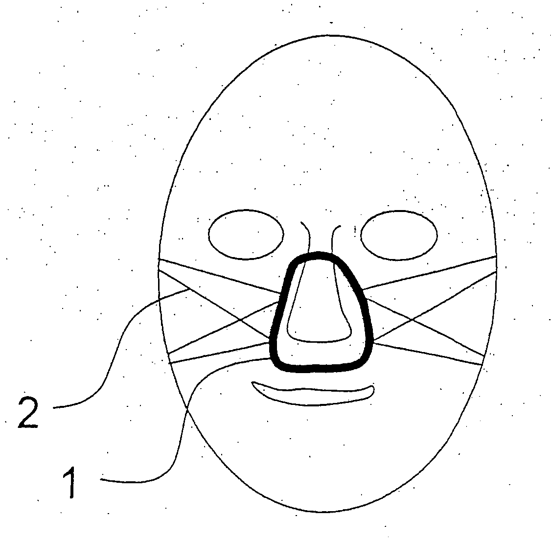
[0034] Referring to the drawings in particular, in exemplary embodiment 1, FIGS. 1 and 2 show two views of a nasal CPAP mask. The mask is equipped with an adhesively acting seal 1, designed here as a silicone lip coated with an adhesive gel. A strap 2 acting as a holding device for fixing the mask on the head is likewise present and transmits part of the needed tensile force to counteract the overpressure in the interior space of the mask body 3.

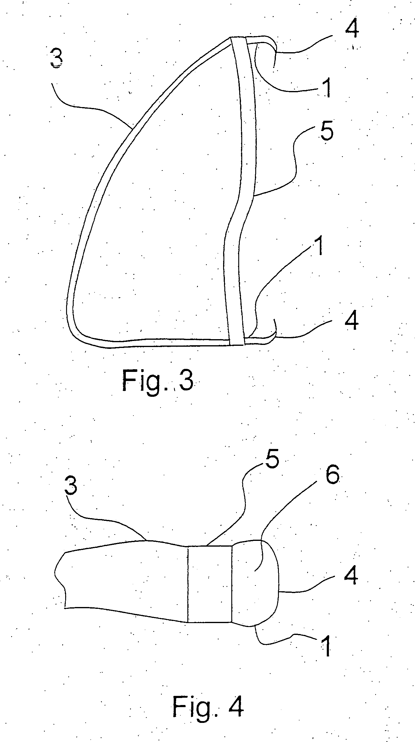
[0035]FIG. 3 shows a similar mask, whose mask body is equipped with a circumferential silicone lip 1, part of which can be folded over such that it acts as a bonding surface 4. The silicone lip 1 is fastened to a moldable frame 5, by which adaptation to the shape of the face can be performed. The frame 5 forms at the same time the closure of the mask body 3.

exemplary embodiment 2

[0036] In exemplary embodiment 2, FIG. 4 shows a breathing mask according to the present invention with a specially designed seal to facilitate the removal of the mask from the face. It includes a possibility of thermally affecting the adhesive force in order to make removal possible at reduced adhesive force. The seal 1 is designed as a flexible tube for this purpose. The outer side of this flexible tube is designed as a bonding surface 4 and is wetted with an adhesive gel, which develops a weak adhesive force below a temperature of 25° C. If this seal is pressed onto the face, sufficient adhesive force will develop in a short time due to the rising temperature. To remove the mask, cool water is sent through the interior 6 of the flexible tube. If the temperature of the bonding surface drops below 25° C. as a result, the mask can be removed from the face in a simple manner because of the reduced adhesive force. The cooling can be brought about by flushing with cool water within the...

exemplary embodiment 3

[0037] In exemplary embodiment 3, FIG. 5 shows a breathing mask according to the present invention with a specially designed seal to facilitate the removal of the mask from the face. It includes a possibility of changing the cross section of the seal 1. The seal 1 is designed as a flexible surface between two webs 7, 7′ for this purpose. If a pressure is admitted into the cavity 8 formed or the volume is sealed, the bonding surface 4, which is coated with an adhesive gel, can be placed on the face for bonding. To remove the mask, the cavity 8 can be evacuated by means of a syringe or a bellows, as a result of which the adhering surface seeks to assume a position 4′ that facilitates the removal of the mask from the skin surface.


PUM


Abstract

A breathing mask with a mask body (3), has a seal (1) at its edge. The seal is placed in contact with the user's face. At least part of the surface of the seal that is in contact with the user's face has an adhesive surface.

Description

CROSS REFERENCE TO RELATED APPLICATIONS [0001] This application claims the benefit of priority under 35 U.S.C. § 119 of DE 10 2004 030 069.0 filed Jun. 23, 2004, the entire contents of which are incorporated herein by reference. FIELD OF THE INVENTION [0002] The present invention pertains to a breathing mask with an adhesive seal, which brings about a sealing action at the time when it is pressed onto the face with a weak pressure. BACKGROUND OF THE INVENTION [0003] Masks sealing in such a way may be used wherever the airways are to be protected from the undesired effect of various substances, which may be inhaled with the breathing air, or where breathing gases, to which medically indicated components are optionally added, are to be specifically introduced. This may be exemplified by breathing masks that are delivered with respirators in the broadest sense of the word. [0004] These include, among other things, devices for patients who require respiratory support for various reasons...

Claims


Application Information

Patent Timeline
Patent Type & Authority Applications(United States)
IPC IPC(8): A41D13/11A61M16/06
CPCA41D13/1146A41D13/1176A61M16/0688A61M2210/0618A61M16/0616A61M16/06A61M2205/0238
Inventor SCHRADER, CORNELIAMEYER, JORG-UWEKULLIK, GOTZHANSMANN, HANS-ULLRICH
Owner DRAGERWERK AG
Why Eureka
Try Eureka