A wireless powering device, an energizable load, a wireless system and a method for a wireless energy transfer

A technology of power supply equipment and wireless energy, which is applied in the fields of excitable loads, wireless systems, and wireless induction power supply equipment to achieve the effect of improving the comfort of use

Inactive Publication Date: 2007-04-18
KONINKLIJKE PHILIPS ELECTRONICS NV
View PDF1 Cites 49 Cited by
  • Summary
  • Abstract
  • Description
  • Claims
  • Application Information

AI Technical Summary

Problems solved by technology

[0012] This known device has the disadvantage that it requires a feedback signal for controlling the output voltage on

Method used


Image

  • A wireless powering device, an energizable load, a wireless system and a method for a wireless energy transfer
  • A wireless powering device, an energizable load, a wireless system and a method for a wireless energy transfer
  • A wireless powering device, an energizable load, a wireless system and a method for a wireless energy transfer

Examples


Embodiment Construction

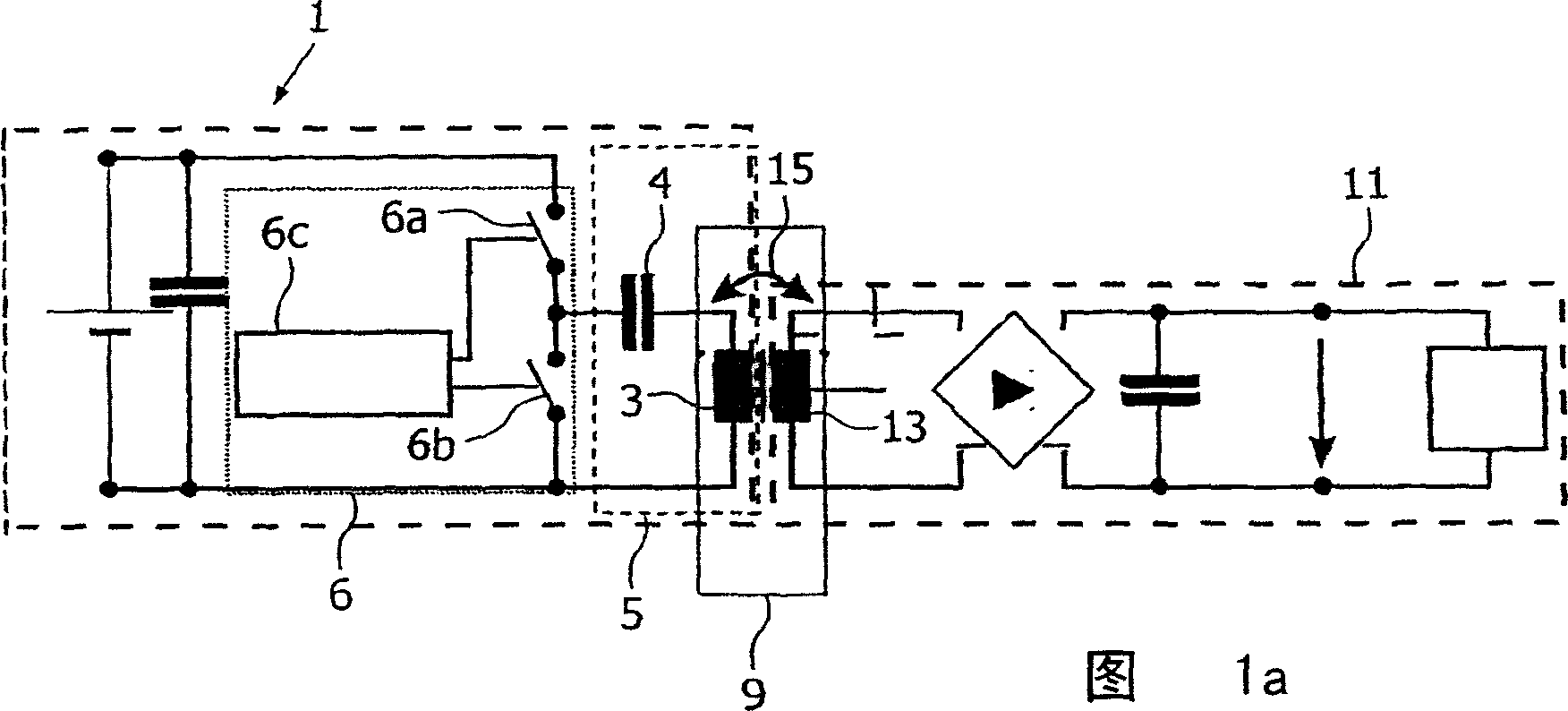
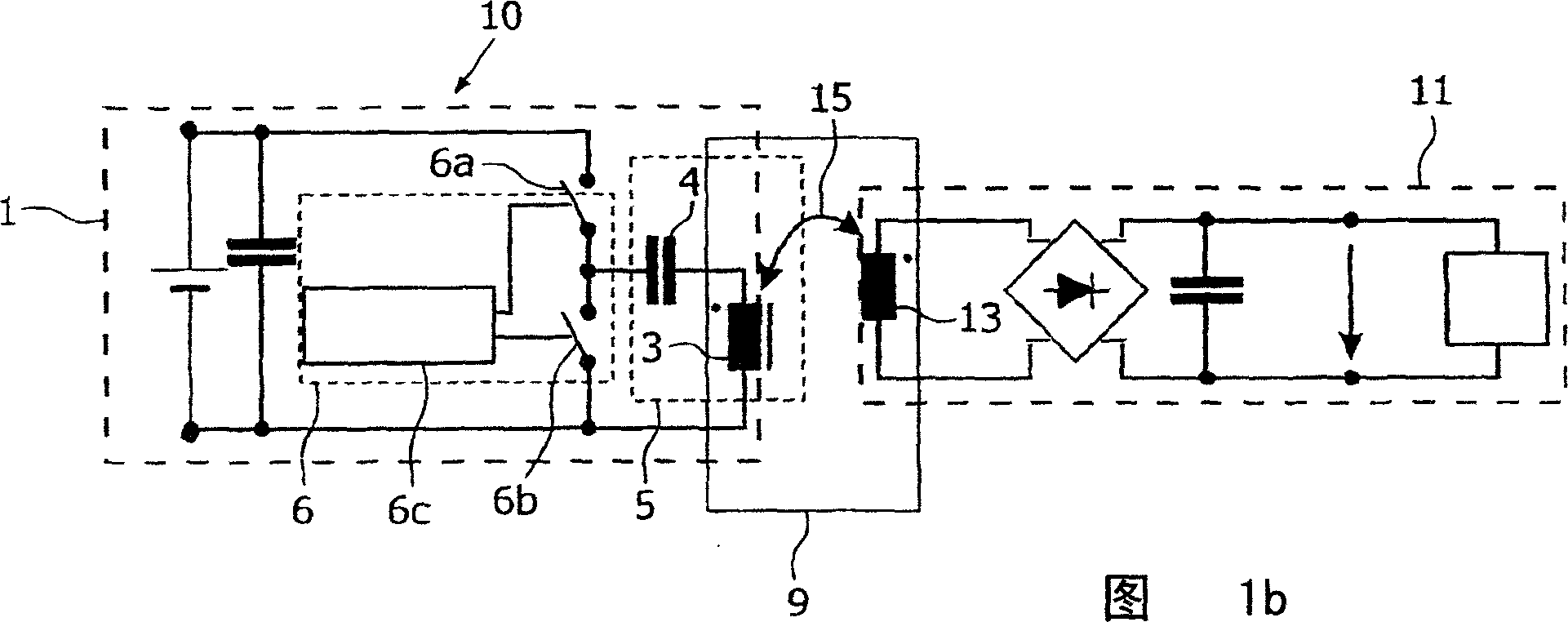
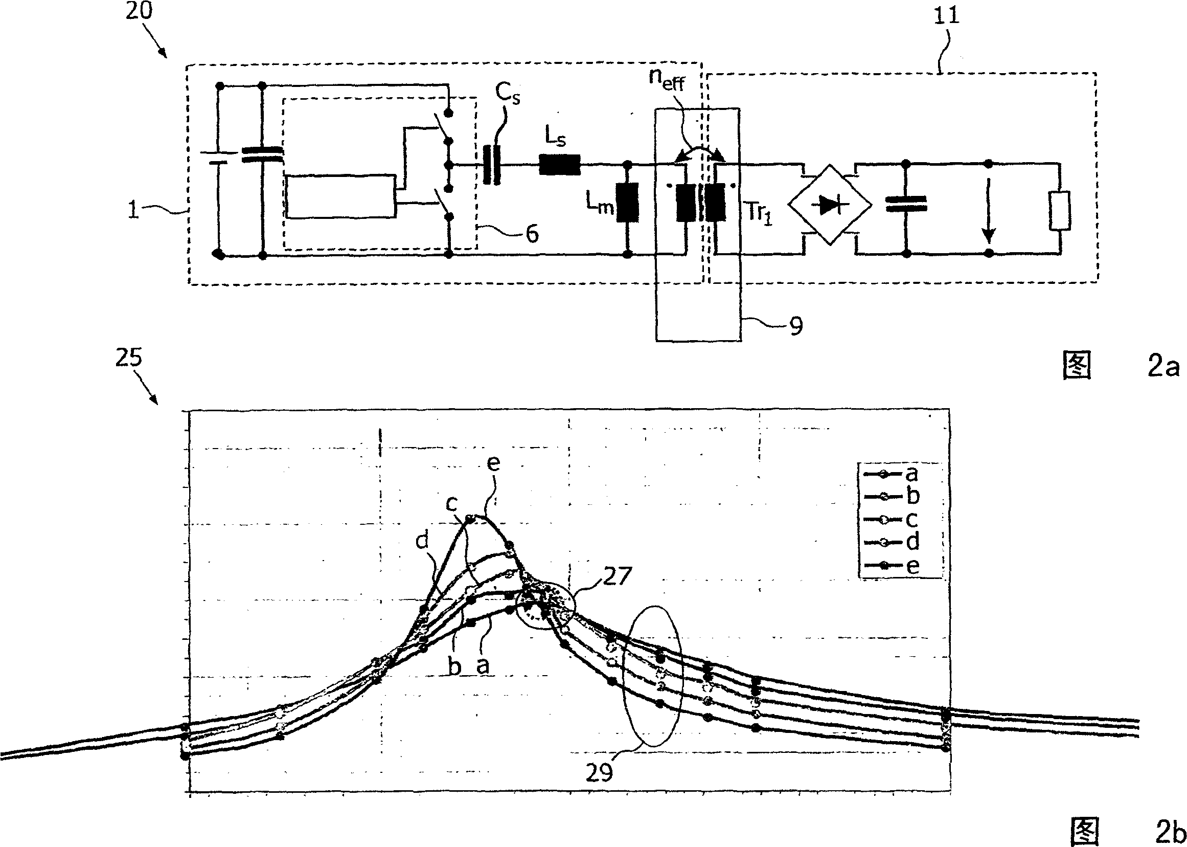
[0070] Fig. 1a shows in a schematic way an embodiment of a circuit of a wireless resonant power supply device according to the invention for a good coupling between the first inductive coil and the inductive coil. The wireless resonant power supply device 1 according to the invention comprises a first inductive coil 3 arranged to form a converter 9 together with an inductive coil 13 excitable to a load 11 . The first inductance coil 3 and the series capacitor 4 are arranged to form a resonant circuit 5 . The resonant circuit 5 may comprise a suitable number of capacitors and coils. The drive means 6 are arranged to operate the resonant circuit at coupling independent points, the concept of which will be explained with reference to Figures 2a and 2b. The drive device 6 comprises a control unit 6c arranged to induce an alternating voltage between the first semiconductor switch 6a and the second semiconductor switch 6b. Preferably, these semiconductor switches are implemented u...


PUM


Abstract

A wireless resonant powering device (1) according to the invention comprises a first inductor winding (3), which is arranged to form a transformer (9) with the inductor winding (13) of the energizable load (11). The first inductor winding (3) is arranged to form a resonant circuit (5), which may comprise a suitable plurality of electric capacitances and coils. The components of the resonant circuit (5) are selected such that the magnetic energy received by the inductor winding (13) damps the energy flow in the resonant circuit so that the induced voltage in the inductor winding (13) is substantially constant and is independent of the magnetic coupling between the first inductor winding (3) and the inductor winding 13 at the operating frequency of the driving means (6). The resonant circuit is driven by the driving means (6), comprising a control unit (6c) arranged to induce an alternating voltage between a first semiconductor switch (6a) and a second semiconductor switch (6b). At the output of the transformer (9) an alternating voltage is generated, which is rectified to a DC-voltage by a diode rectifier, filtered by an output capacitance. The resonant circuit (5) is operable on its coupling independent point by the driving means (6). This figure schematically illustrates a situation, where a variable coupling between the first inductor winding (3) and the inductor winding (13) exists. The invention further relates to a wireless inductive powering device, an energizable load, a wireless system and a method for wireless power transfer.

Description

technical field [0001] The present invention relates to a wireless resonant power supply device for wireless energy transfer to an excitable load comprising an inductor winding, said device comprising a resonant circuit. [0002] The invention also relates to a wireless inductive powering device for wireless energy transfer to an energizable load comprising an inductive coil, said wireless inductive powering device comprising a transducer having: [0003] - soft magnetic core; [0004] - A first induction coil, housed in a soft magnetic core and conceived to interact in phase with the induction coil when it is positioned in the vicinity of said magnetic core in order to constitute a converter. [0005] The invention also relates to energizable loads. [0006] The invention also relates to wireless systems. [0007] The invention also relates to a method for wireless energy transfer from a wireless resonant power supply to an energizable load comprising an inductive coil, sa...

Claims


Application Information

Patent Timeline
IPC IPC(8): H01F38/14H02J7/02H02J5/00H02M3/337
CPCH02M3/337H01F38/14H02J5/005H02J7/00034H02J7/00712H02J50/40H02J50/80H02J50/12H02J7/00304H02M3/33571H02M3/01H02J50/90
Inventor E·瓦芬-施米德特H·赖特C·德佩G·绍尔莱恩德B·阿克曼
Owner KONINKLIJKE PHILIPS ELECTRONICS NV
Why Eureka
Try Eureka