Common damper hub for valve bodies

a technology of damper hub and valve body, which is applied in the direction of shock absorbers, functional valve types, transportation and packaging, etc., can solve the problems of adverse effects on the damper damping characteristics, and achieve the effect of reducing the number of components stocked

Inactive Publication Date: 2005-12-29
IMAN +1
View PDF6 Cites 4 Cited by
  • Summary
  • Abstract
  • Description
  • Claims
  • Application Information

AI Technical Summary

Benefits of technology

[0008] Accordingly, the above mentioned provides a modular damper design that reduces the number of components stocked for different dampers while providing consistent loading of the piston valve assembly.

Problems solved by technology

The damping characteristics of the damper are adversely affected if the deflection discs are not properly loaded against the piston.

Method used


Image

  • Common damper hub for valve bodies
  • Common damper hub for valve bodies
  • Common damper hub for valve bodies

Examples


Embodiment Construction

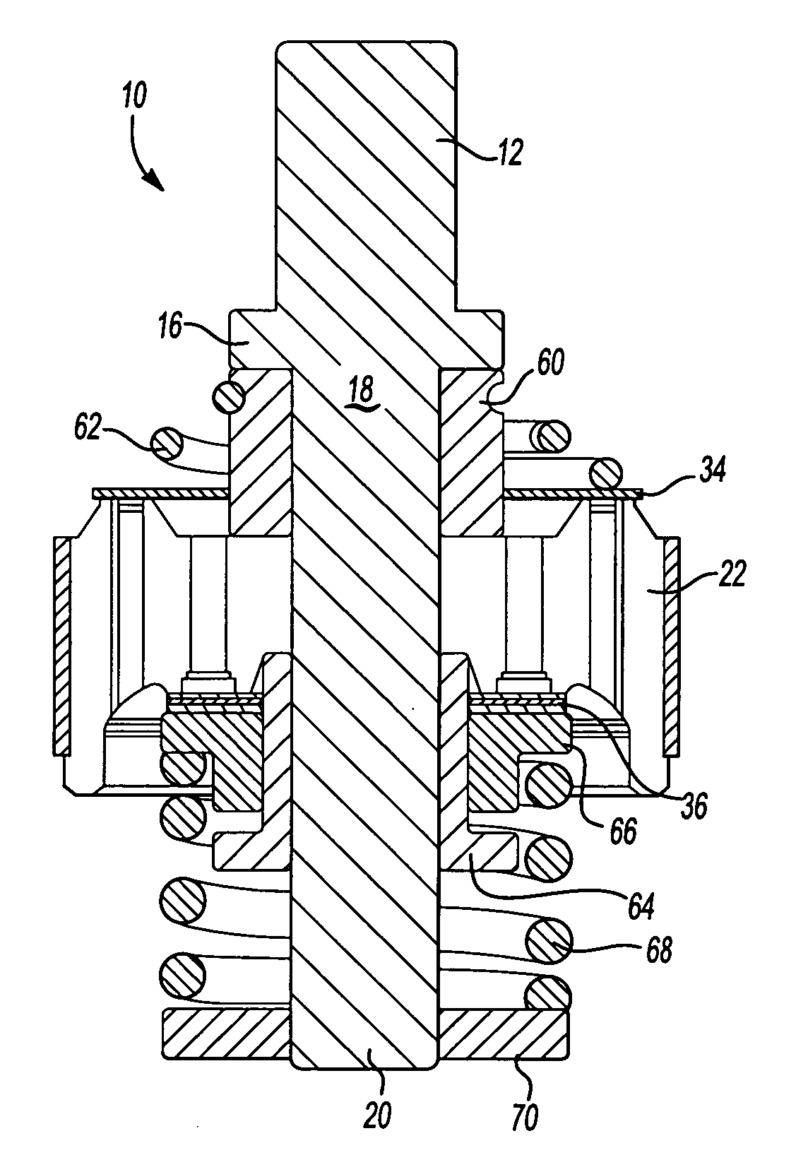
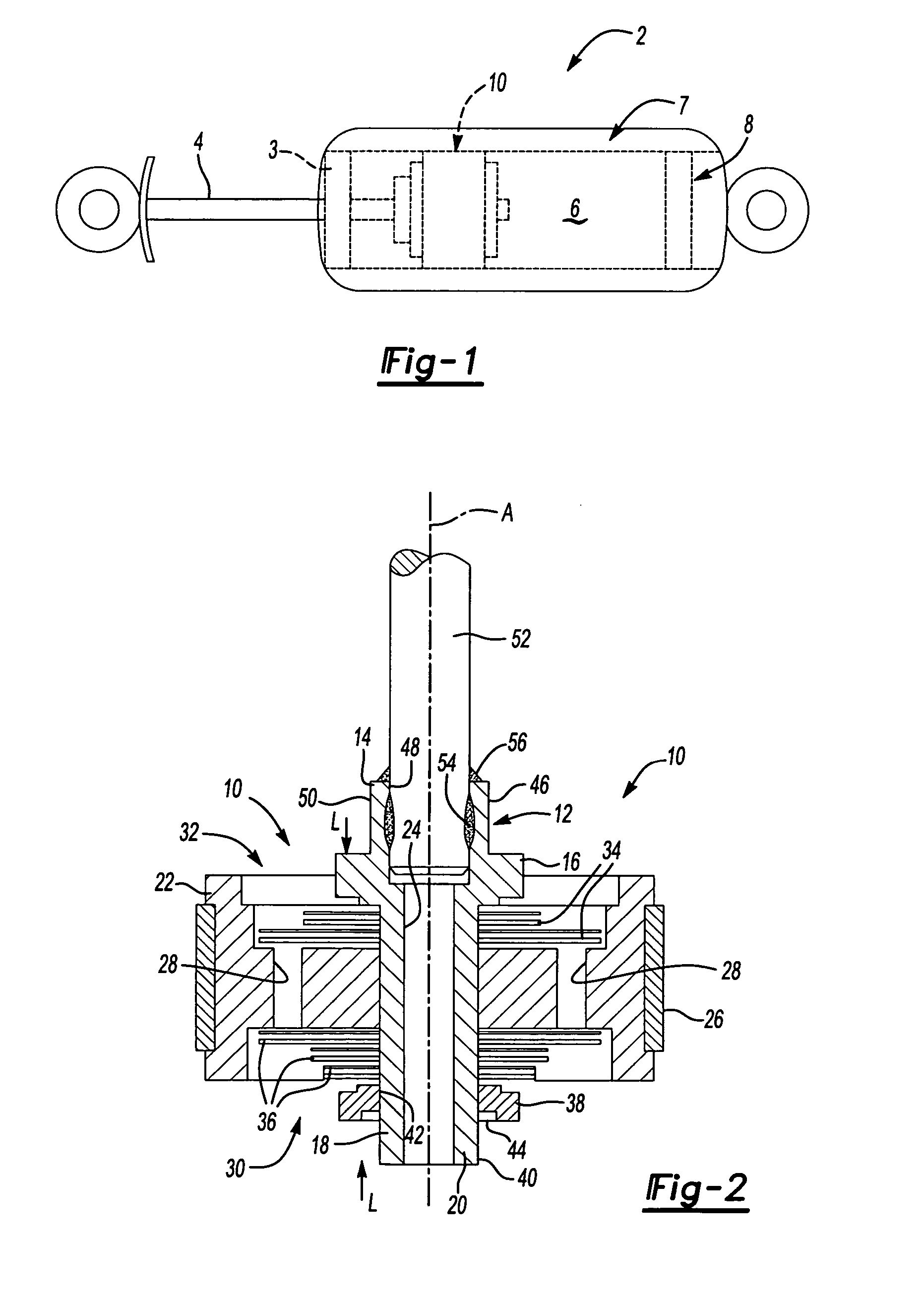
[0022] A twin tube shock absorber 2 is shown in FIG. 1. The shock absorber 2 schematically depicts a cylinder head 3 at one end slidingly receiving a rod 4, as is well known in the art. An end of the rod 4 is secured to the inventive piston valve assembly 10, which is arranged in a fluid chamber 6. During a compression stroke, the piston valve assembly 10 moves towards a base valve 8, which regulates the flow of fluid from the fluid chamber 6 to an outer chamber 7. As will be appreciated from the description below, the piston assembly 10 and base valve 8 incorporate an inventive hub 12, which is shown in FIGS. 2-12.

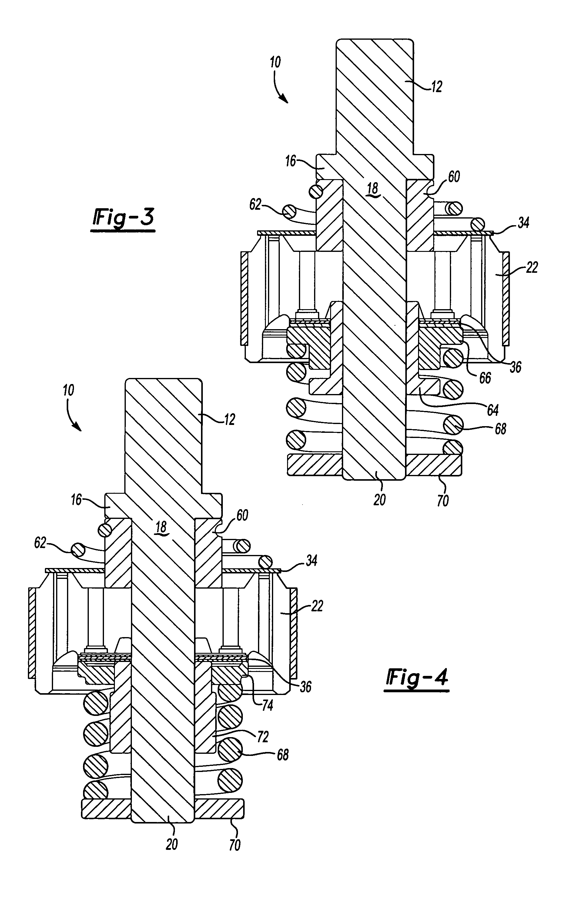
[0023] A piston valve assembly 10 of the present invention is shown in FIG. 2. The assembly 10 includes an inventive hub 12 that is designed to be used with different sized pistons and deflection discs to facilitate a more modular damper assembly. The hub 12 includes a first end 14 that is adapted to receive a piston rod. The first end 14 includes a shoulder 16 and a nec...


PUM


Abstract

A piston valve assembly for a damper comprises a piston having a central hole and a fluid passageway spaced from the hole. A deflection disc having a central aperture is aligned with the hole. The deflection disc is arranged adjacent to the piston and at least partially blocks the fluid passageway for regulating the flow of hydraulic fluid between the fluid chambers when installed in the damper. A hub, common across different dampers, includes a neck that is arranged in the hole and the aperture of the deflection disc. A retainer abuts an unthreaded outer surface of the hub. During assembly, the retainer is received on the cylindrical outer surface in a slip fit relation. The deflection disc and pistons are loaded to a predetermined clamp load. The retainer is secured to the outer surface by a securing material such as a weld bead.

Description

BACKGROUND OF THE INVENTION [0001] This invention relates to dampers such as vehicle suspension shock absorbers, struts and the like. More particularly, the invention relates to a common hub design for piston and base valve arrangements enabling a more modular damper. [0002] Dampers such as shock absorbers and struts are used in vehicles to absorb inputs from the roadway to provide a desirable vehicle ride. Typically, vehicle dampers employ a piston that moves through a cylinder having hydraulic fluid. The fluid flows through fluid passageways and valves in the piston, which absorbs the roadway inputs in the form of heat. The piston size, valves, and piston rod are selected based upon the particular vehicle and vehicle application, which requires the damper OEM to stock numerous parts for different vehicles and even for different suspension packages for the same vehicle. [0003] One common type of piston valve assembly uses deflection discs on either side of the piston. The deflectio...

Claims


Application Information

Patent Timeline
Patent Type & Authority Applications(United States)
IPC IPC(8): F16F9/32F16F9/348F16K17/18
CPCF16F9/348F16F9/3228Y10T137/7771
Inventor CARLSTEDT, ROBERT P.SIESEL, JAMES J.SLEDZ, CHRISTOPHER T.
Owner IMAN
Why Eureka
Try Eureka