Liquid crystal display device protection structure for electronic equipment

a technology of electronic equipment and display device, which is applied in the direction of instruments, portable computer details, electrical apparatus casings/cabinets/drawers, etc., can solve the problems of cracks, unfavorable mobile phone expansion, and increased outline shape size, etc., and achieves the effect of convenient fixation

Inactive Publication Date: 2005-12-29
FUJITSU TOSHIBA MOBILE COMM LTD
View PDF0 Cites 205 Cited by
  • Summary
  • Abstract
  • Description
  • Claims
  • Application Information

AI Technical Summary

Benefits of technology

[0014] The present invention has been made in view of the above-mentioned problems, and may provide a liquid crystal display device protection structure for electronic equipment that allows the outline size to be minimized while preventing damage to the liquid crystal display device.

Problems solved by technology

With the mobile phone A described above in which a large viewing window Do is formed in the upper inner casing Da, the upper inner casing Da is likely to be deflected or deformed relatively easily when the display screen protection cover I is heavily depressed from the outside, which may cause the display screen protection cover I to be brought into contact with the liquid crystal display device E, resulting in that damages such as cracks are created in the display device E.
Possible solutions to such a problem are to increase the wall thickness of the upper cabinet D including that of the upper inner casing Da thereby enhancing the strength, or to increase the clearance between the display screen Ef of the liquid crystal display device E and the display screen protection cover I. However, these solutions inevitably cause another problem of an undesired increase in the size of the mobile phone A.
Therefore, the size of the outline shape is inevitably increased.
However, because the upper cabinet has a high rigidity and lacks the flexibility as stated above, when the upper cabinet is subjected to a great impact force due to such a cause as dropping, the impact force is neither absorbed nor attenuated by the upper cabinet, but directly acts on the liquid crystal display device E′.
As a result, the liquid crystal display device E′, which comprises a glass substrate, and the plastic material portion itself of the equipment cabinet may be cracked or otherwise damaged.

Method used


Image

  • Liquid crystal display device protection structure for electronic equipment
  • Liquid crystal display device protection structure for electronic equipment
  • Liquid crystal display device protection structure for electronic equipment

Examples


first embodiment

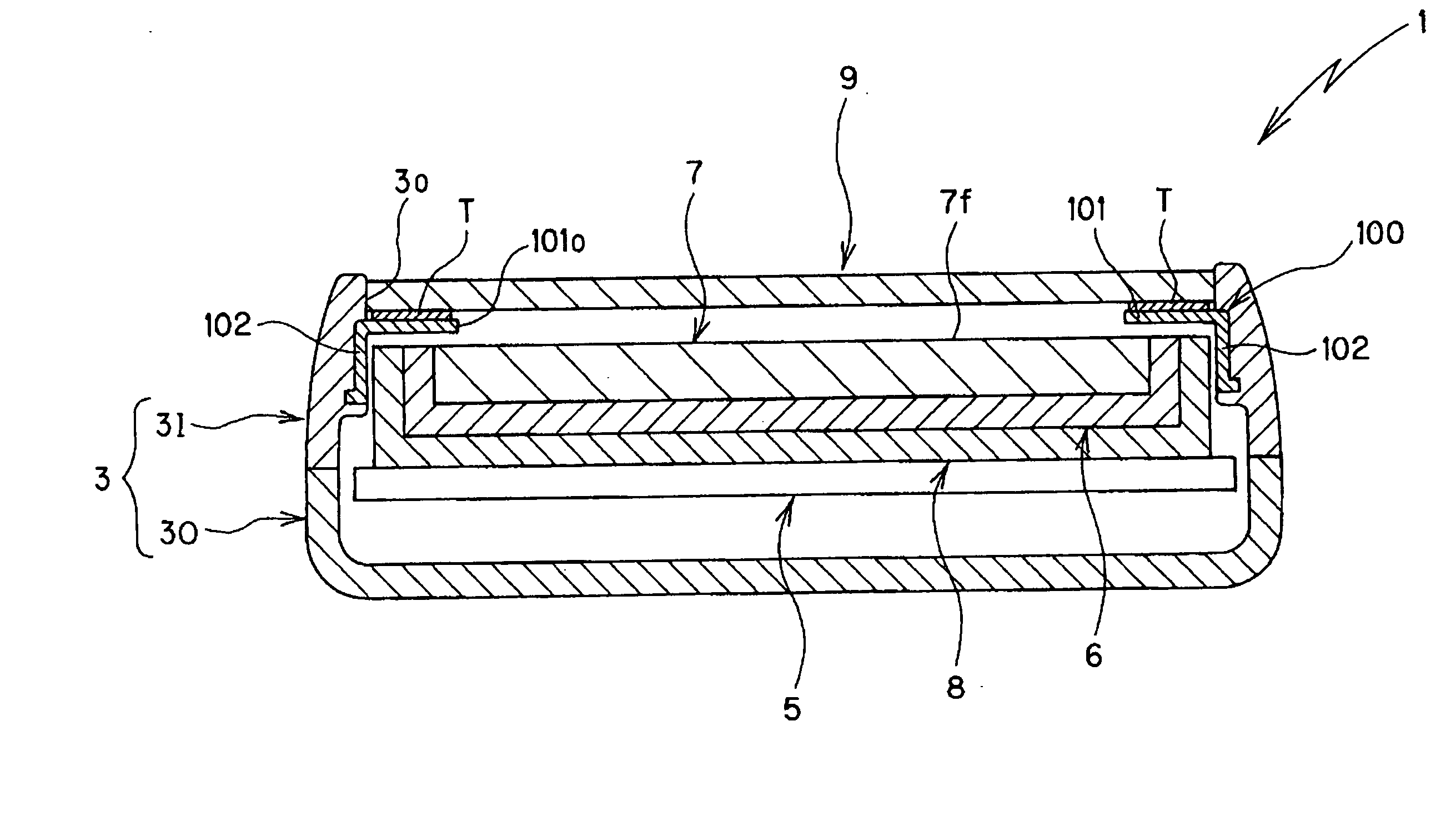
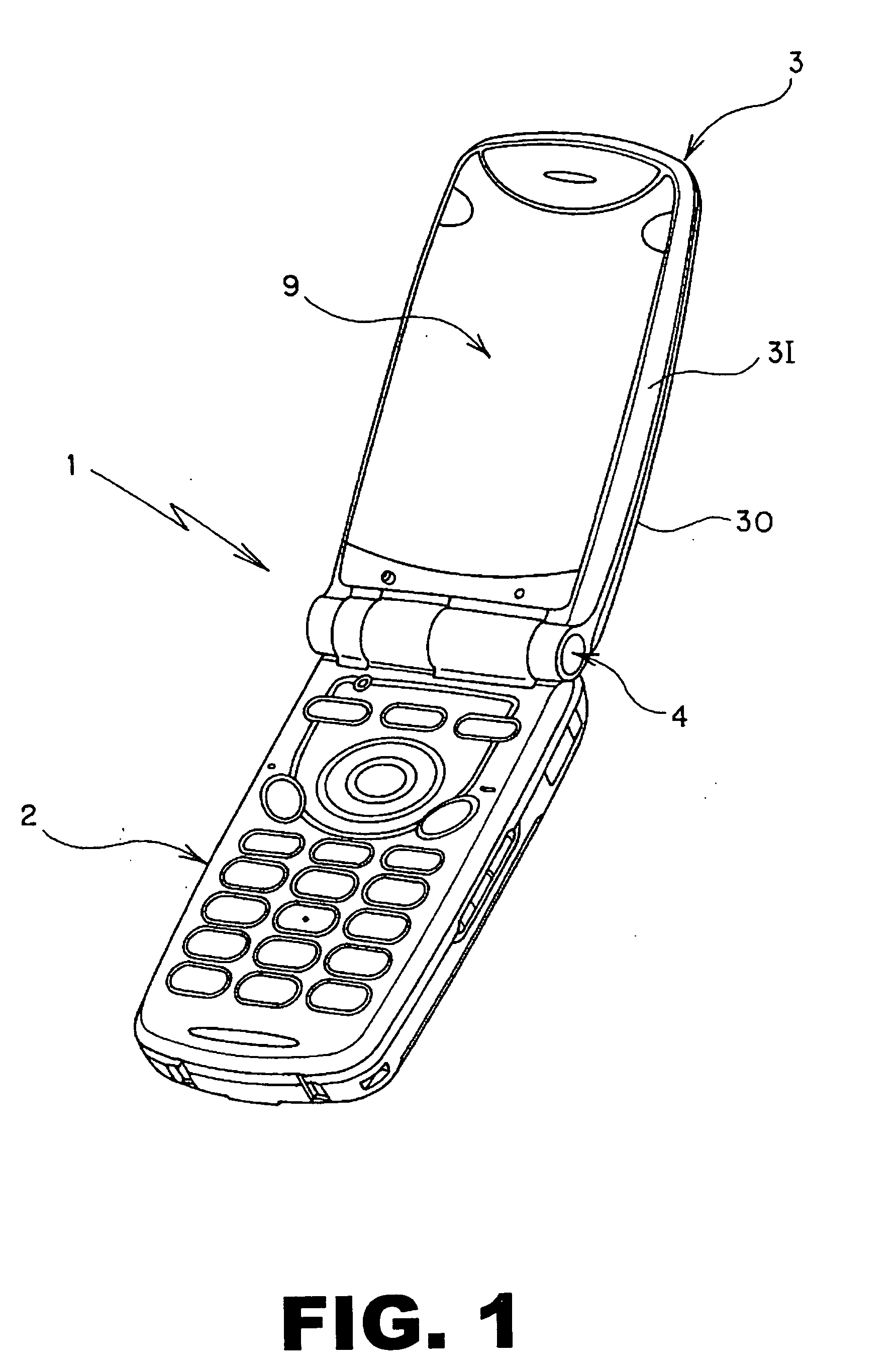
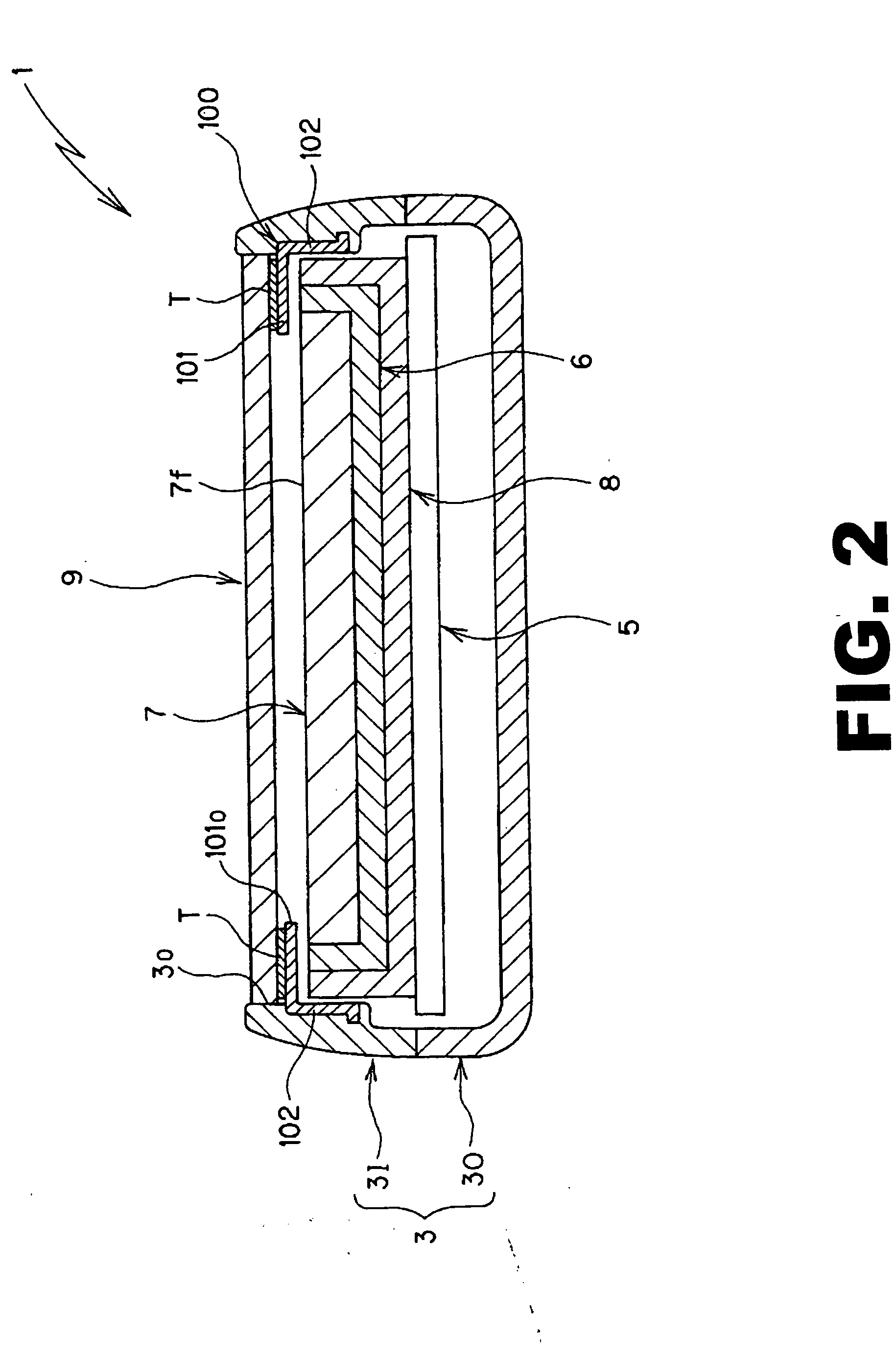
[0058]FIG. 1 through FIG. 6 show a first embodiment where a liquid crystal display device protection structure relating to the present invention is applied to a foldable mobile phone, which is a type of electronic equipment. This mobile phone 1 comprises a lower cabinet 2 provided with a variety of controllers, and an upper cabinet 3 accommodating a liquid crystal display device 7 later described. The lower cabinet 2 and the upper cabinet 3 are connected to each other through a hinge 4 such that the foldable mobile phone can be freely opened and closed.

[0059] The upper cabinet 3, which constitutes the equipment cabinet together with the lower cabinet 2, comprises an upper inner casing 3I and an upper outer casing 3O which are assembled to each other, and the upper inner casing 3I and the upper outer casing 3O are both manufactured in a desired shape by injection molding of plastic material.

[0060] As shown in FIG. 2 and FIG. 3, a circuit board 5 is accommodated in the inside of the ...

second embodiment

[0075]FIG. 7 to FIG. 12 show a second embodiment where a liquid crystal display device protection structure relating to the present invention is applied to a mobile phone, which is a type of electronic equipment. An upper cabinet (equipment cabinet) 13 in the foldable mobile phone 10 comprises an upper inner casing 13I and an upper outer casing 13O which are assembled to each other, and the upper inner casing 13I and the upper outer casing 13O are both manufactured in a desired shape by injection molding of plastic material.

[0076] As shown in FIG. 7 to FIG. 9, a circuit board 15 is accommodated in the inside of the upper cabinet 13, and on the component mounting surface of the circuit board 15, a backlight device 16 and a liquid crystal display device 17 constituting a liquid crystal display unit are mounted in a prescribed location through a holder 18.

[0077] In the upper inner casing 13I of the upper cabinet 13 is formed a viewing window 13o which is faced with the display screen ...

third embodiment

[0086]FIG. 13 to FIG. 18 show a third embodiment where a liquid crystal display device protection structure relating to the present invention is applied to a mobile phone, which is a type of electronic equipment. An upper cabinet (equipment cabinet) 23 in this foldable mobile phone 20 comprises an upper inner casing 23I and an upper outer casing 23O which are assembled to each other. The upper inner casing 23I and the upper outer casing 23O are both manufactured in a desired shape by injection molding of plastic material.

[0087] As shown in FIG. 13 to FIG. 15, a circuit board 25 is accommodated in the inside of the upper cabinet 23. On the component mounting surface of the circuit board 25, a backlight device 26 and a liquid crystal display device 27 constituting a liquid crystal display unit are mounted in a prescribed location through a holder 28.

[0088] In the upper inner casing 23I of the upper cabinet 23 is formed a viewing window 23o which is faced with the display screen 27f o...


PUM

PropertyMeasurementUnit
mechanical strengthaaaaaaaaaa
shapeaaaaaaaaaa
thicknessaaaaaaaaaa

Abstract

A liquid crystal display device protection structure for electronic equipment having an equipment cabinet made of a plastic material in which a liquid crystal display device is accommodated, the equipment cabinet formed with a viewing window so as to be faced with a display screen of the liquid crystal display device, comprises a reinforcing frame made of a material having a mechanical strength higher than that of the plastic material used for the equipment cabinet, and having a frame shape matched to a periphery of the viewing window, the reinforcing frame being integrally fixed to the equipment cabinet so as to be matched to the periphery of the viewing window, and a display screen protection cover which covers the viewing window and is mounted to the reinforcing frame.

Description

CROSS-REFERENCE TO RELATED APPLICATIONS [0001] This application is based upon and claims the benefit of priority from the prior Japanese Patent Application No. 2004-190025 filed on Jun. 28, 2004; the entire contents of which are incorporated herein by reference. FIELD OF THE INVENTION [0002] The present invention relates to a liquid crystal display device protection structure for electronic equipment, and specifically, to a protection structure for preventing the damage to the liquid crystal display device, which can be applied to electronic equipment including a liquid crystal display device accommodated in the inside of an equipment cabinet made of a plastic material, a viewing window which is faced with the display screen of the liquid crystal display device and is formed in the equipment cabinet, and a display screen protection cover which covers the viewing window. BACKGROUND OF THE INVENTION [0003] In a mobile phone, which is a type of electronic equipment, a liquid crystal di...

Claims


Application Information

Patent Timeline
Patent Type & Authority Applications(United States)
IPC IPC(8): G02F1/1333G02F1/1335G06F1/16
CPCG02F1/133308G02F2201/503G06F1/1637G06F1/1616G06F1/16
Inventor YAMAZAKI, NOBUYUKI
Owner FUJITSU TOSHIBA MOBILE COMM LTD
Why Eureka
Try Eureka