Check patentability & draft patents in minutes with Patsnap Eureka AI!

Method for the parallax-free centering of an optical element and device for carrying out said method

a technology of optical elements and parallax-free centering, which is applied in the field of parallax-free centering of optical elements, can solve the problem that the process does not serve as the centering of semi-finished products, and achieve the effect of simplifying the process steps and simplifying the centering and alignmen

Active Publication Date: 2005-12-29
CARL ZEISS VISION INT GMBH
View PDF10 Cites 2 Cited by
  • Summary
  • Abstract
  • Description
  • Claims
  • Application Information

AI Technical Summary

Benefits of technology

[0005] Consequently, it is an object of the invention to provide a method that permits a simplification of the process steps and simplifies the centering and alignment at a centering and mounting device.
[0007] A simple and accurate aligning or centering at the mounting device can be performed with the aid of the engravings provided with the semifinished product / spectacle lens. The process step of “stamping” the semifinished product is therefore eliminated.

Problems solved by technology

Also, this process does not serve for centering semifinished products.

Method used


Image

  • Method for the parallax-free centering of an optical element and device for carrying out said method
  • Method for the parallax-free centering of an optical element and device for carrying out said method
  • Method for the parallax-free centering of an optical element and device for carrying out said method

Examples


Embodiment Construction

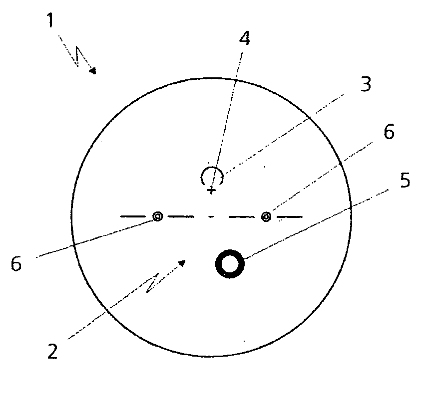
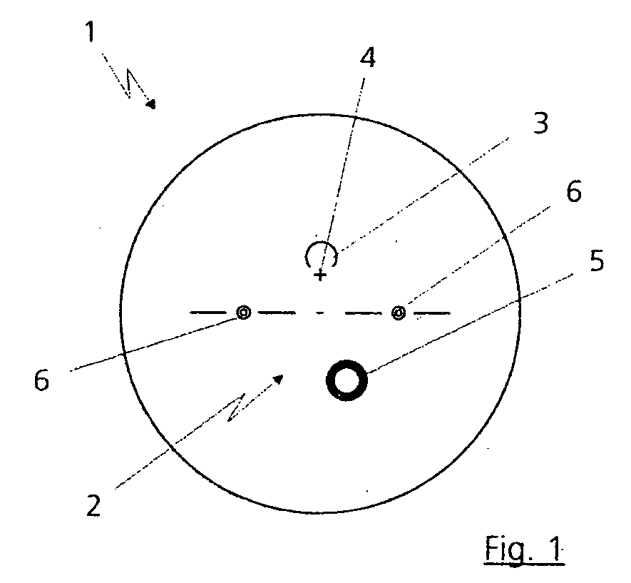
[0012]FIG. 1 shows as prior art a semifinished product 1 that is provided with a stamped image 2. The stamped image 2 is also that stamped image which an ophthalmic optician requires for monitoring the distance power and the near power. According to the prior art, this stamped image 2 consists of a distance measuring circle 3, the ophthalmic optician being able to use a centering cross 4 for the subsequent monitoring of the distance power. Using the known concave-side measuring method, the ophthalmic optician can subsequently measure the required near measured value in a near measuring circle 5. After removal of the stamped image 2, the ophthalmic optician can reconstruct all the reference and measured points with the aid of lens engravings 6, so-called permanent engravings, and a measuring template. The permanent engravings 6 also identify the spectacle lens type, a spectacle lens identification such as, for example, T66 for the refractive index 1.665 being engraved in each case be...


PUM


Abstract

In a method for the parallax-free centering of an optical element, in particular a semifinished product of a future spectacle lens, on a holder of a centering or mounting device, the optical element is provided with engravings. The centering of the optical element is performed with the aid of the engravings.

Description

BACKGROUND OF THE INVENTION [0001] The invention relates to a method for the parallax-free centering of an optical element, in particular a semifinished product of a future spectacle lens, on a holder of a centering or mounting device, the optical element being provided with engravings. DESCRIPTION OF THE RELATED ART [0002] It is already known from the general prior art that semifinished products of non-individual progressive lenses are produced in a casting process. During the casting process, engravings are also introduced into the front side of the semifinished product. The engravings permit an orientation of the semifinished product which is required because of the free form surface of the future progressive lens. After the casting process and possibly surface treatments, the semifinished products are provided with a stamped image and aligned at a mounting device or a blocking device. During the blocking process, the semifinished product is connected to a mount or a blocking pie...

Claims


Application Information

Patent Timeline
Patent Type & Authority Applications(United States)
IPC IPC(8): B24B9/14B24B13/005G02C13/00
CPCB24B9/146G02C13/005G02C13/003B24B13/0055
Inventor ZAISER, MICHAEL
Owner CARL ZEISS VISION INT GMBH
Features
  • R&D
  • Intellectual Property
  • Life Sciences
  • Materials
  • Tech Scout
  • Unparalleled Data Quality
  • Higher Quality Content
  • 60% Fewer Hallucinations
Learn More