Ultrafast optical delay lines using a time-prism pair

a time-prism pair and optical delay technology, applied in non-linear optics, instruments, optics, etc., can solve the problem of limited delay-to-pulse width ratio, avoid input pulse broadening effects, and increase the delay-to-pulse width ratio

Inactive Publication Date: 2005-12-29
CORNELL RES FOUNDATION INC
View PDF1 Cites 18 Cited by
  • Summary
  • Abstract
  • Description
  • Claims
  • Application Information

AI Technical Summary

Benefits of technology

The patent describes a new way to create a delay line using fiber optics. By using a special type of material called a sinusoidally driven LiNbO3 phase modulator and a dispersion fiber, the delay line can be made all-fiber, meaning it uses only fiber optics to create the delay. This new method also avoids a problem called input pulse broadening, which occurs when using linear propagation between the time-prisms. By using soliton propagation, the delay-to-pulse-width ratio is increased, resulting in a more effective delay line.

Problems solved by technology

The patent text discusses the need for optical delay lines that can scan at faster rates for various applications such as optical coherence tomography, optical metrology, interferometry, and telecommunications. The technical problem is to find a way to achieve higher scanning rates for optical delay lines.

Method used


Image

  • Ultrafast optical delay lines using a time-prism pair
  • Ultrafast optical delay lines using a time-prism pair
  • Ultrafast optical delay lines using a time-prism pair

Examples


Embodiment Construction

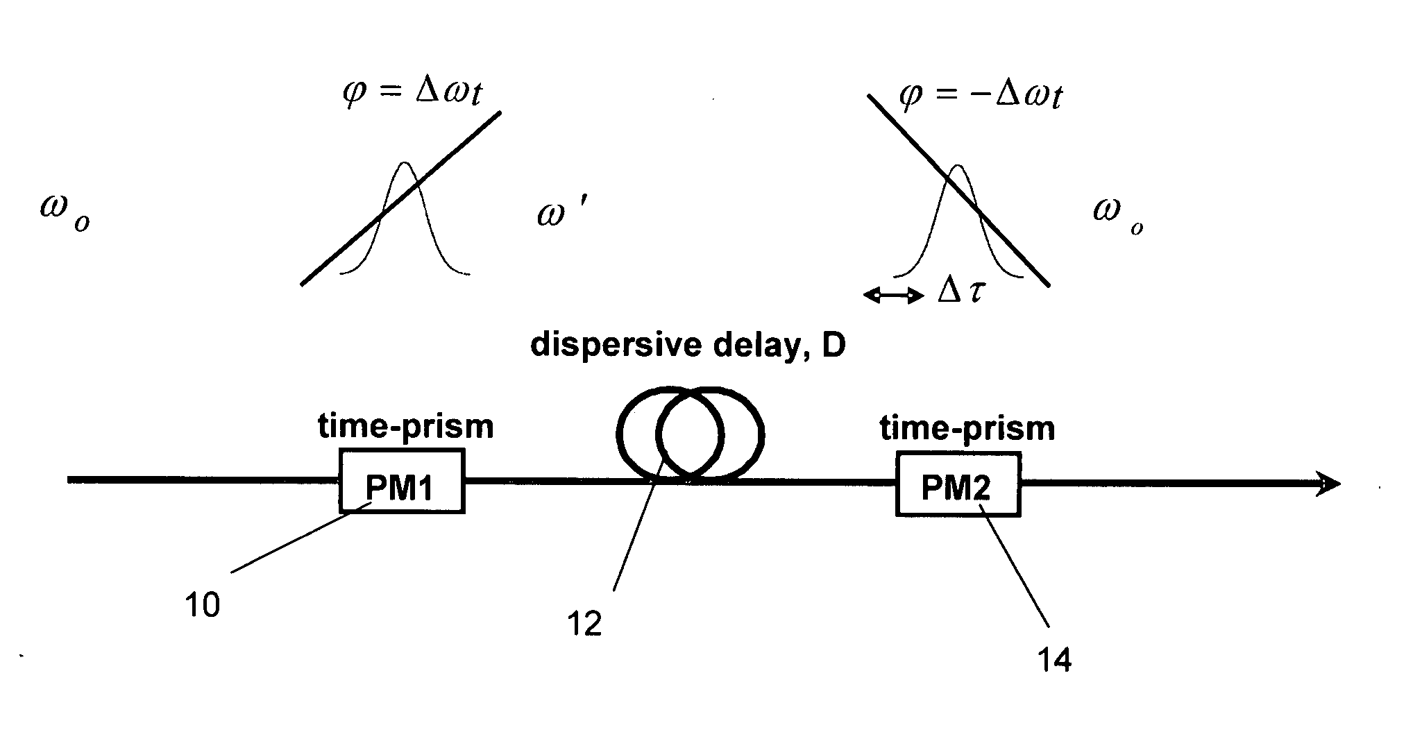
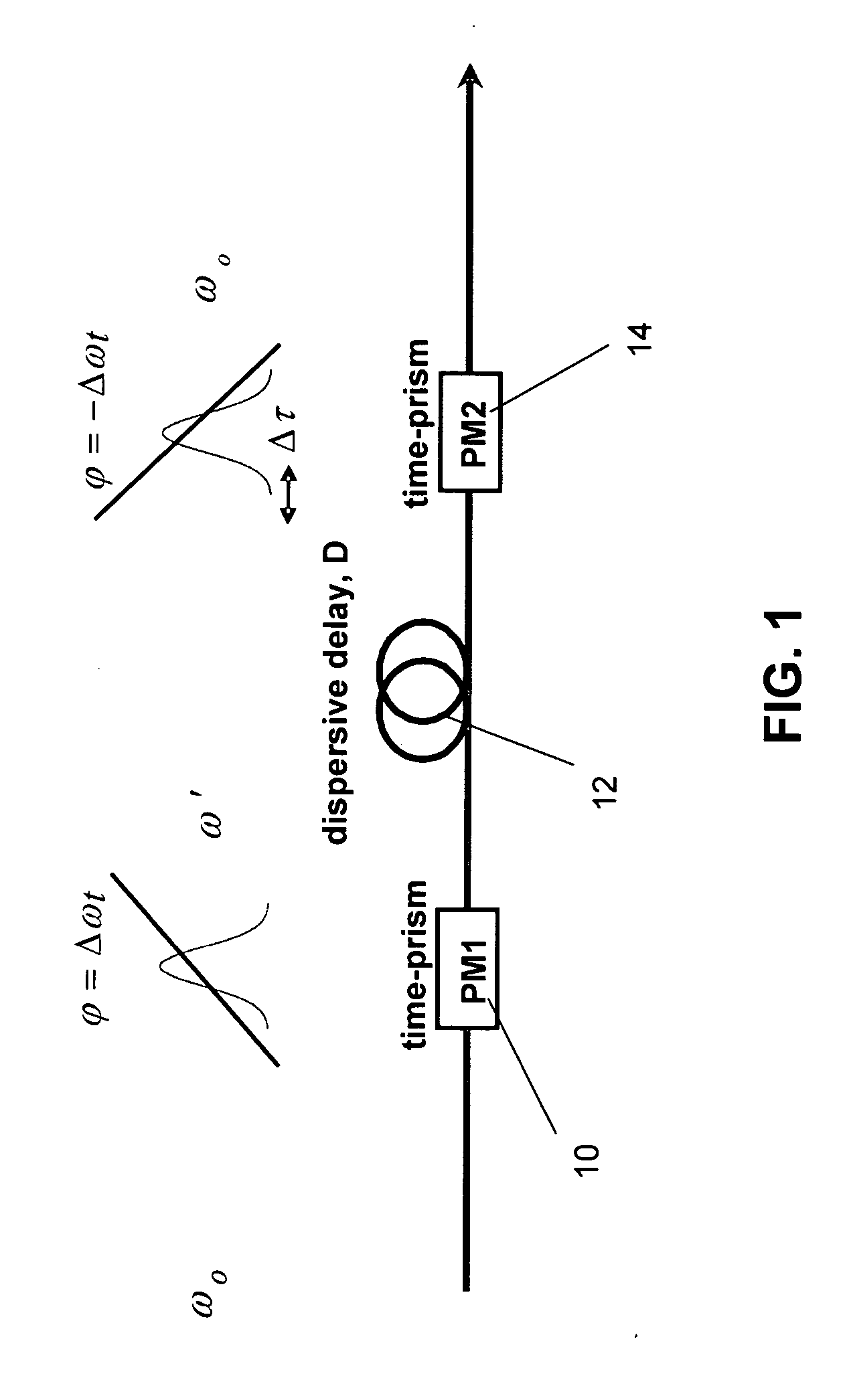
[0015] With reference now to a more detailed description of a number of preferred embodiments of the present invention, FIG. 1 is a schematic illustration of the key fundamental elements that are present in all embodiments of the present invention. An incoming pulse train of know frequency co is input to a first phase modulator 10, which acts as a first time-prism and shifts the frequency of the incoming pulse train by an amount that is proportional to a drive voltage that is applied to the phase modulator 10. The pulse train now has a frequency ω′ and is fed through a dispersion element 12, which, depending on the embodiment of the invention employed, can be a dispersion fiber such as single mode fiber (SMF) or dispersion compensating fiber (DCF), a Fiber Bragg Grating (FBG), a grating pair or any other suitable dispersion element in order to impart a delay to the frequency shifted pulse train as it passes there through. Finally, the delayed pulse train passes through a second phas...


PUM


Abstract

A programmable, ultrafast optical delay line based on reversible frequency conversion uses a time-prism pair and no moving parts. A first electro-optic phase modulator acting as a first time-prism shifts the frequency of an incoming pulse train. The pulse train passes through a dispersion element, such as a dispersive fiber, which delays the pulse train by an amount that is directly proportional to the magnitude of the frequency shift, which in turn is proportional to the magnitude of the phase modulator drive voltage. A second electro-optic phase modulator is driven π out of phase to the first modulator and restores the frequency of the delayed pulse train to the original frequency of the incoming pulse train. To reduce pulse broadening effects and enhance performance further, soliton propagation inducing elements can be employed between the time-prisms.

Description


Claims


Application Information

Patent Timeline
Owner CORNELL RES FOUNDATION INC
Why Eureka
Try Eureka