Side-emitting collimator

a collimator and side-emitting technology, applied in the field of lenses, can solve the problems of limited light output and undesirable appearan

Active Publication Date: 2005-12-29
WHELEN ENGINEERING COMPANY
View PDF3 Cites 120 Cited by
  • Summary
  • Abstract
  • Description
  • Claims
  • Application Information

AI Technical Summary

Benefits of technology

[0010] These surface shapes and relationships are an example of surfaces that efficiently gather light from an LED and re-direct that light into a pair of opposed collimated beams perpendicular to the optical axis of the LED. The invention should not be construed as being limited to the particular disclosed surface shapes.

Problems solved by technology

Older models of LED's produced limited quantities of light over a relatively narrow viewing angle centered around an optical axis of the LED.
Such an arrangement typically does not fill the light fixture, resulting in an undesirable appearance consisting of bright spots arranged against an unlit background.

Method used


Image

  • Side-emitting collimator
  • Side-emitting collimator
  • Side-emitting collimator

Examples


Embodiment Construction

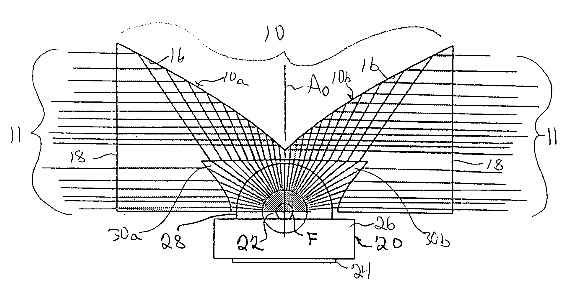
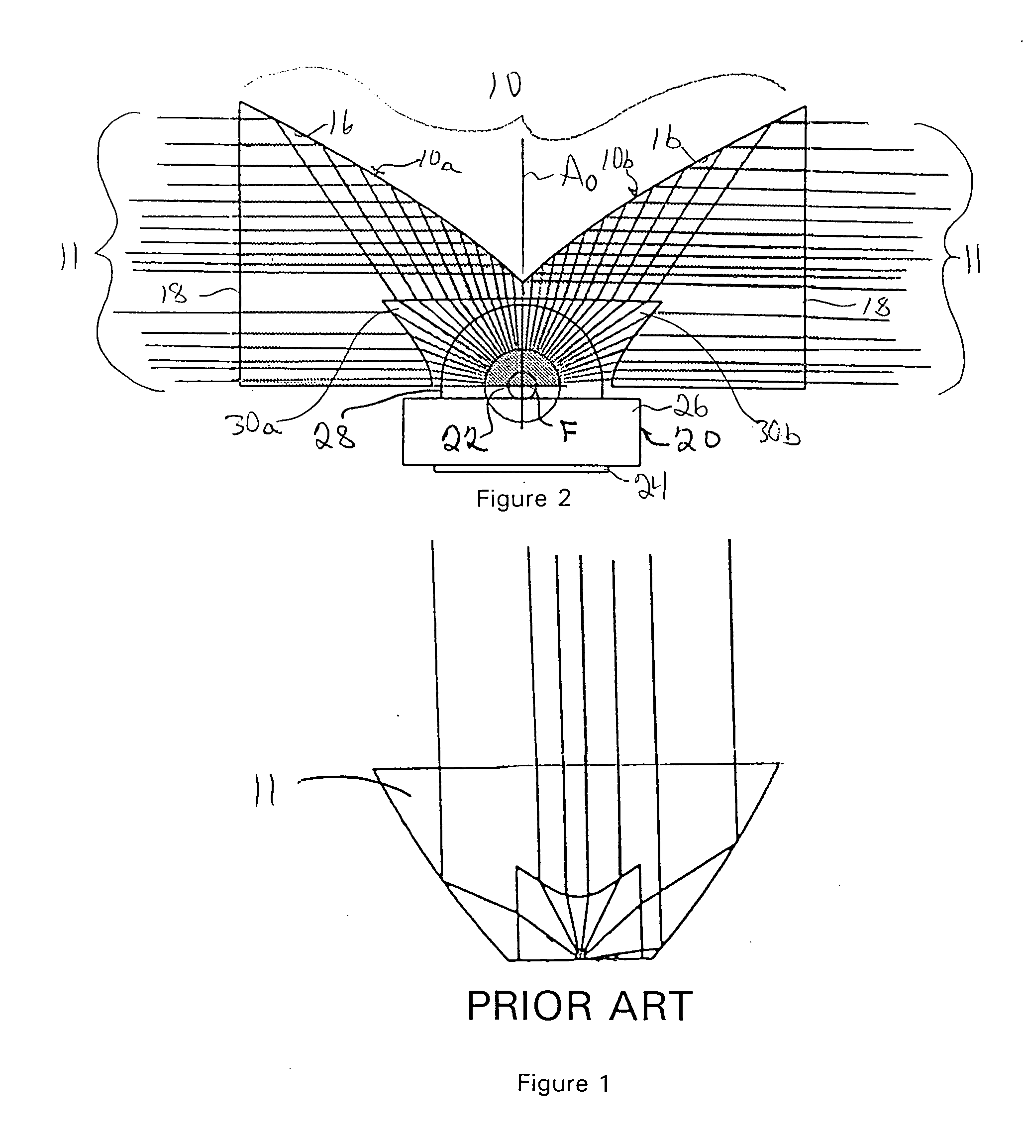
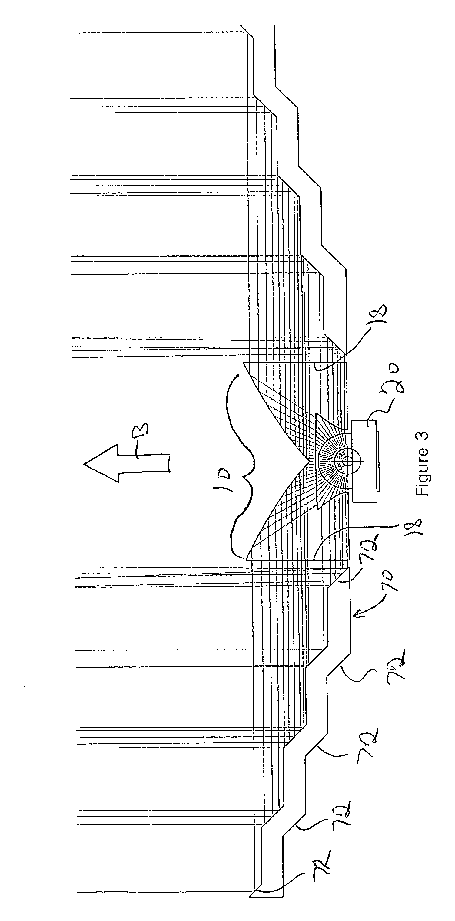
[0021] Exemplary embodiments of the side-emitting collimator will now be described with reference to FIGS. 2-6. FIG. 2 shows an exemplary side emitting collimator 10 in conjunction with an LED light source 20. The side-emitting collimator 10 organizes light from the LED 20 into a pair of opposed collimated beams 11 perpendicular to the optical axis AO of the LED 20. The LED 20 includes a base 26 above a heat-transmissive slug 24. A lens 28 extends upwardly from the base 26. The LED lens 28 surrounds a point of light emission 22. The point of light emission 22 in an LED 20 is defined by a semi-conductor chip (not shown) which emits light when energized by an electrical current. The illustrated LED lens 28 is of the high-dome or “lambertian” shape. An LED with this lens shape emits light in a half dome surrounding the optical axis AO of the LED. The side-emitting collimator 10 is constructed about a focal point F that preferably coincides with the point of light emission 22 of the LED...


PUM


Abstract

A side-emitting collimator employs a combination of refraction and internal reflection to organize light from a light source into oppositely directed collimated beams. A light source chamber over the light source is defined by substantially cylindrical and aspheric refracting surfaces positioned to gather light into the collimating lens. The aspheric refracting surfaces redirect a portion of the light from the light source into a direction perpendicular to the optical axis of the light source. The substantially cylindrical surfaces refract light from the light source onto an aspheric upper reflecting surface. Light incident upon the aspheric upper reflecting surface is collimated into a direction perpendicular to the optical axis of the light source. The side-emitting collimator includes mirror image collimator halves, each producing a collimated beam. The collimator halves are rotationally symmetric about a common axis of symmetry above a plane including the axis of symmetry.

Description

BACKGROUND OF THE INVENTION [0001] 1. Field of the Invention [0002] The present invention relates generally to lenses for distributing light from a light source and more particularly to a lens for changing the effective direction of light emission for a light source. [0003] 2. Description of the Related Art [0004] The use of LED's in warning and signaling lights is well known. Older models of LED's produced limited quantities of light over a relatively narrow viewing angle centered around an optical axis of the LED. These LED's were typically massed in compact arrays to fill the given illuminated area and provide the necessary light output. Modern LED's produce significantly greater luminous flux per component, permitting fewer LED's to produce the luminous flux required for many warning and signaling applications. It is known to arrange a small number of high-output LED's in a light fixture and provide each high-output LED with an internally reflecting collimating lens. The collima...

Claims


Application Information

Patent Timeline
Patent Type & Authority Applications(United States)
IPC IPC(8): F21S4/00F21S8/10F21V5/00F21V5/04F21V7/00F21V13/04F21V29/00G02B17/08
CPCF21S4/008F21V29/87F21S48/218F21S48/328F21V5/04F21V7/005F21V7/0091F21V13/04F21V29/004F21Y2101/02G02B17/002G02B17/006Y10S362/80G02B19/0066G02B19/0071G02B19/0028G02B19/0061F21V29/74F21S48/215F21V29/763F21S4/28F21Y2115/10F21S43/14F21S43/15F21S45/47
Inventor SMITH, TODD J.
Owner WHELEN ENGINEERING COMPANY
Why Eureka
Try Eureka