
Self-testing power supply apparatus, methods and computer program products

Inactive Publication Date: 2005-12-29
POWERWARE
View PDF7 Cites 46 Cited by
  • Summary
  • Abstract
  • Description
  • Claims
  • Application Information

AI Technical Summary

Benefits of technology

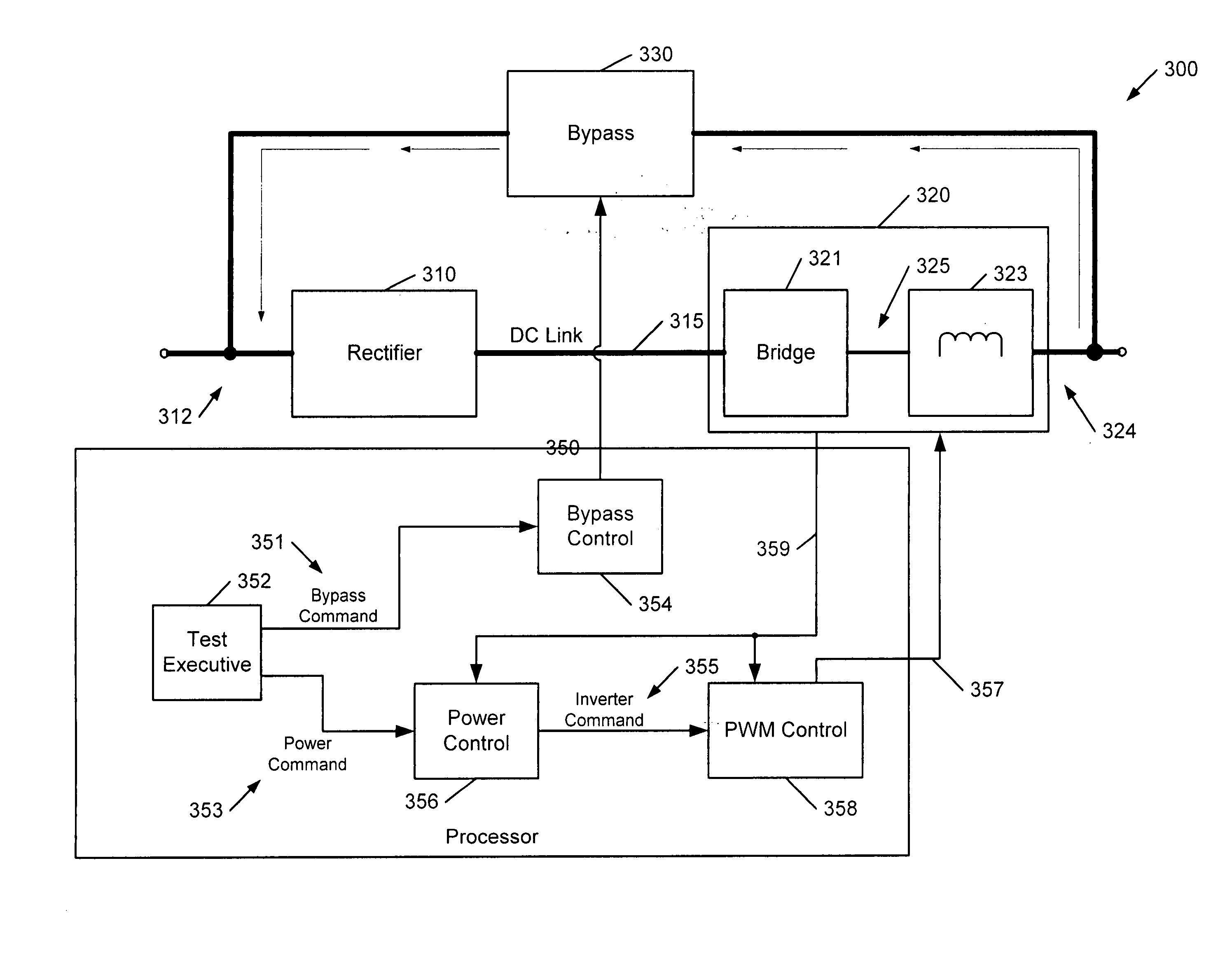
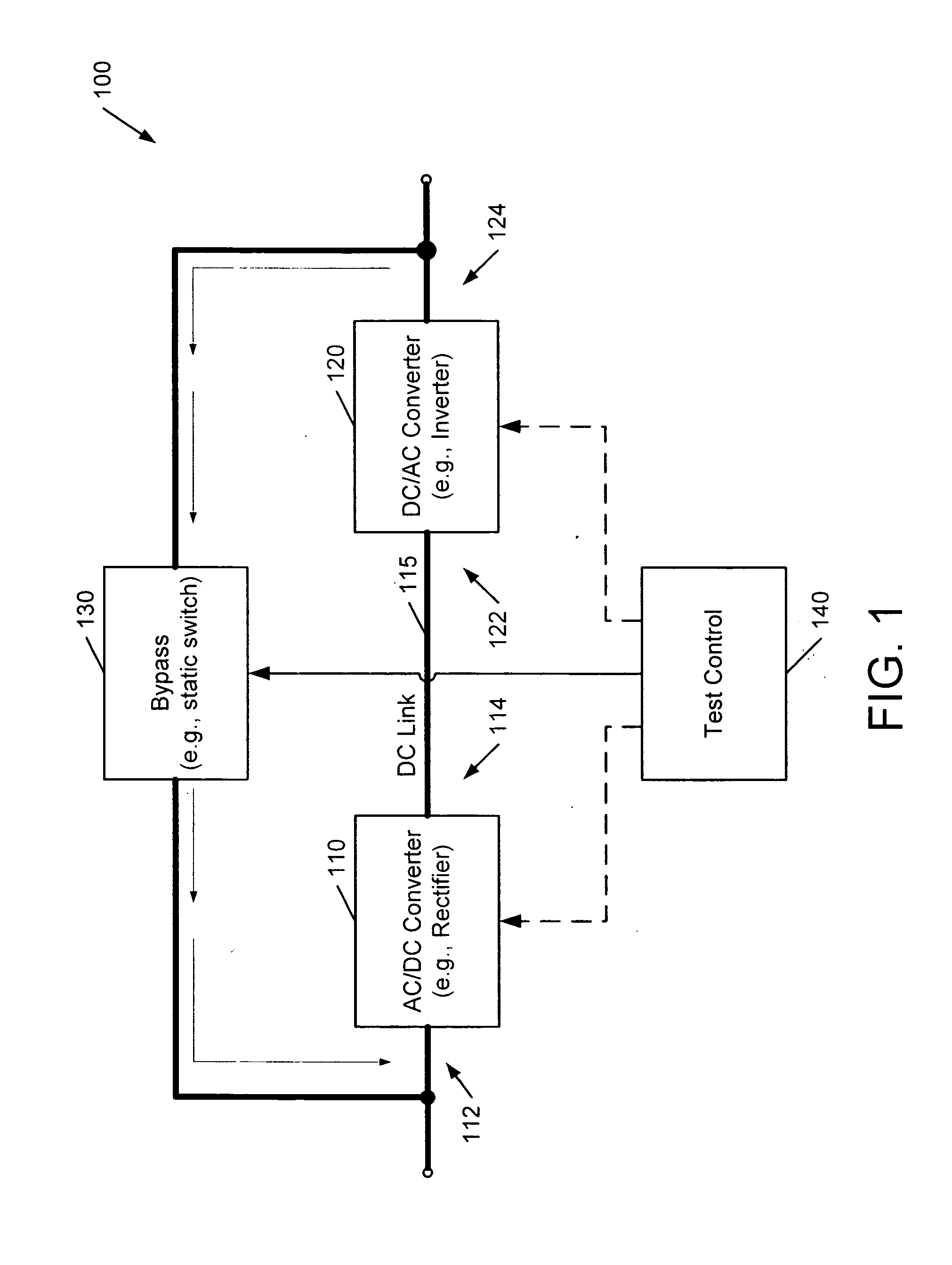
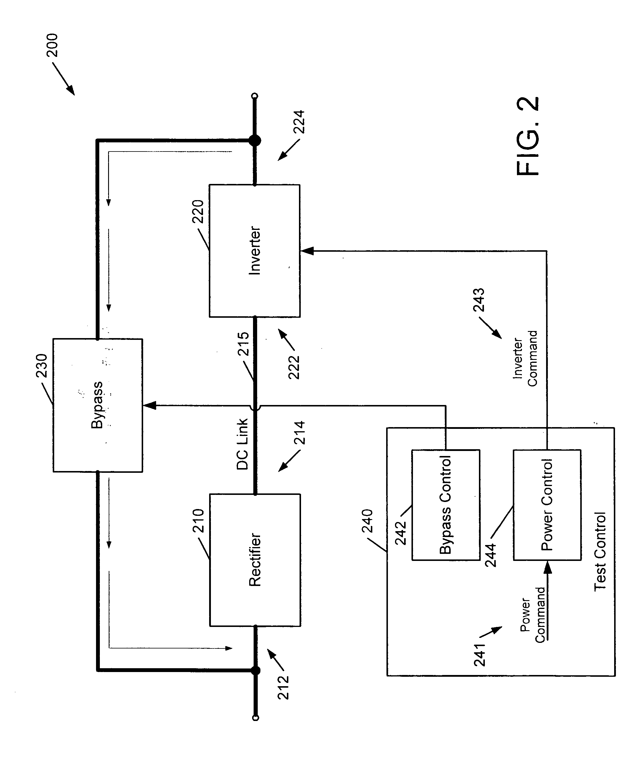
[0008] In further embodiments, power is transferred from the output of the DC/AC converter circuit to the input of the AC/DC converter circuit via the bypass circuit while the input of the AC/DC converter circuit is coupled to the AC power source, e.g., to perform load testing of the apparatus while receiving sufficient power from the AC source to make up for losses in the apparatus. In other embodiments, power is transferred from the output of the DC/AC converter circuit to the input of the AC/DC converter circuit via the bypass circuit while the input of the AC/DC converter circuit is decoupled from the AC power source, e.g., using a battery or other DC source to make up for system losses. In further embodiments, power may be transferred from the output of the DC/AC converter circuit via the bypass circuit for purposes of testing, while power is also provided to a load coupled to the output of the DC/AC converter circuit. In this manner, maintenance and other tests may be performed while maintaining a critical load. In further embodiments, power is transferred from the output of the inverter circuit via the bypass circuit to conduct a test of a DC power source coupled to the DC link, e.g., by conveying current from the DC source to an external AC source via the bypass circuit.
[0009] In additional embodiments of the invention, a power supply apparatus includes an AC/DC converter circuit having an input configured to be coupled to an AC source, a DC/AC converter circuit having an input coupled to an output of the AC/DC converter circuit by a DC link, and a bypass circuit operative to couple

Problems solved by technology

Performing such tests may require extensive infrastructure, including the loads themselves and a sufficiently high-capacity utility infrastructure to supply the power for the testing.
Additionally, significant energy costs may be entailed in such testing, as the energy delivered to the test load in load testing is often dissipated as heat.
Each of these techniques, however, utilize specialized test equipment that can lead to extra cost, and which can make the test techniques less useful for field testing.

Method used


Image

  • Self-testing power supply apparatus, methods and computer program products
  • Self-testing power supply apparatus, methods and computer program products
  • Self-testing power supply apparatus, methods and computer program products

Examples


Embodiment Construction

[0016] Specific exemplary embodiments of the invention now will be described with reference to the accompanying drawings. This invention may, however, be embodied in many different forms and should not be construed as limited to the embodiments set forth herein; rather, these embodiments are provided so that this disclosure will be thorough and complete, and will fully convey the scope of the invention to those skilled in the art. In the drawings, like numbers refer to like elements. It will be understood that when an element is referred to as being “connected” or “coupled” to another element, it can be directly connected or coupled to the other element or intervening elements may be present. Furthermore, “connected” or “coupled” as used herein may include wirelessly connected or coupled. As used herein the term “and / or” includes any and all combinations of one or more of the associated listed items.

[0017] The terminology used herein is for the purpose of describing particular embo...


PUM


Abstract

A power supply apparatus, such as an on-line UPS, includes an AC / DC converter circuit having an input configured to be coupled to an AC source, a DC / AC converter circuit having an input coupled to an output of the AC / DC converter circuit by a DC link, and a bypass circuit operative to couple and decouple the output of the DC / AC converter circuit to and from the input of the AC / DC converter circuit. Power is transferred from the output of DC / AC converter circuit via the bypass circuit to conduct a test of the apparatus, such as a factory or field load test. For example, power may be circulated around a loop including the AC / DC converter circuit, the DC / AC converter circuit and the bypass circuit to conduct the test in order to test these components under load. A status of such components may be determined responsive to the test. In further embodiments, such components may be calibrated responsive to the test.

Description

[0001] The invention relates to power supplies, and more particularly, to testing of power supplies. [0002] A typical conventional large-capacity “on-line” UPS may include an AC / DC converter (e.g., a rectifier) that is configured to be coupled to an AC power source, such as a utility source, and a DC / AC converter (e.g., an inverter) that is coupled to the AC / DC converter by a DC link and which produces an AC voltage at an output (load) bus of the UPS. The UPS may further include a bypass circuit, e.g., a static switch, which can be used to couple the AC power source directly to the output bus of the UPS, such that the AC / DC converter and DC / AC converter are bypassed. The bypass circuit can be used, for example, to provide an economy mode of operation and / or to provide power to the load when either or both of the converters are damaged or inoperative. [0003] Factory testing of such a UPS is often performed with a resistive, reactive load and / or a non-linear test load. Performing such...

Claims


Application Information

Patent Timeline
IPC IPC(8): G01R31/40H02J9/06
CPCH02J9/062G01R31/40Y02P80/10
Inventor PFITZER, HANS-ERIKJONSSON, RUNE LENNARTTRACY, JOHN G.CHAVEZ, MIGUEL E.TASSITINO, FREDERICK JR.ANDERSON, JASON S.
Owner POWERWARE
Learn More