Image processing apparatus and image processing method

a technology of image processing and image processing, applied in the field of digital signal processing, can solve the problems of image quality deterioration, difficult to determine a suitable encoding parameter sure and stably, and large hardware load, and achieve the effect of high quality

Inactive Publication Date: 2005-12-29
CANON KK
View PDF8 Cites 18 Cited by
  • Summary
  • Abstract
  • Description
  • Claims
  • Application Information

AI Technical Summary

Benefits of technology

[0010] In view of the above problem in the conventional art, the present invention provides an image processing apparatus and an image processing method which makes high quality image processing possible for the image data of any dynamic ranges.

Problems solved by technology

Since each image does not always have both the white level and the black level in a screen by the above-described method, it is difficult to determine a suitable encoding parameter certainly and stably.
The apparatus needs to calculate the density histogram and there is a problem that there are large loads on hardware (such as a memory and a computing element) and software.
If the still image and the moving image are concatenated and edited, the image quality deterioration, such as the reduction of contrast or over-contrast (it means that the image is too bright or too dark), is caused from the difference of the dynamic range.
Thus, using the above-described apparatuses and methods, it is difficult to obtain a good quality edit of an image.

Method used


Image

  • Image processing apparatus and image processing method
  • Image processing apparatus and image processing method
  • Image processing apparatus and image processing method

Examples


first embodiment

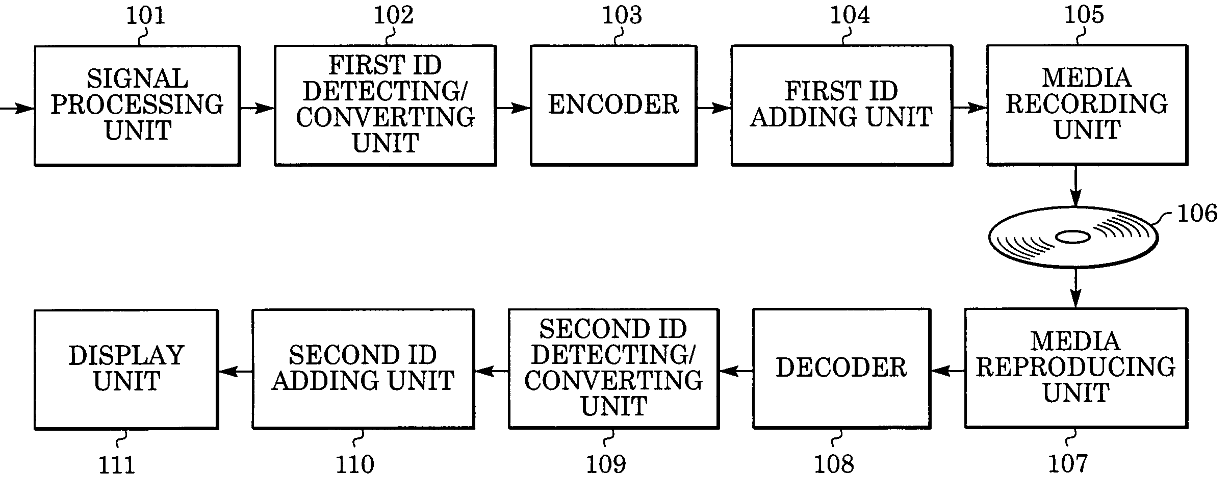
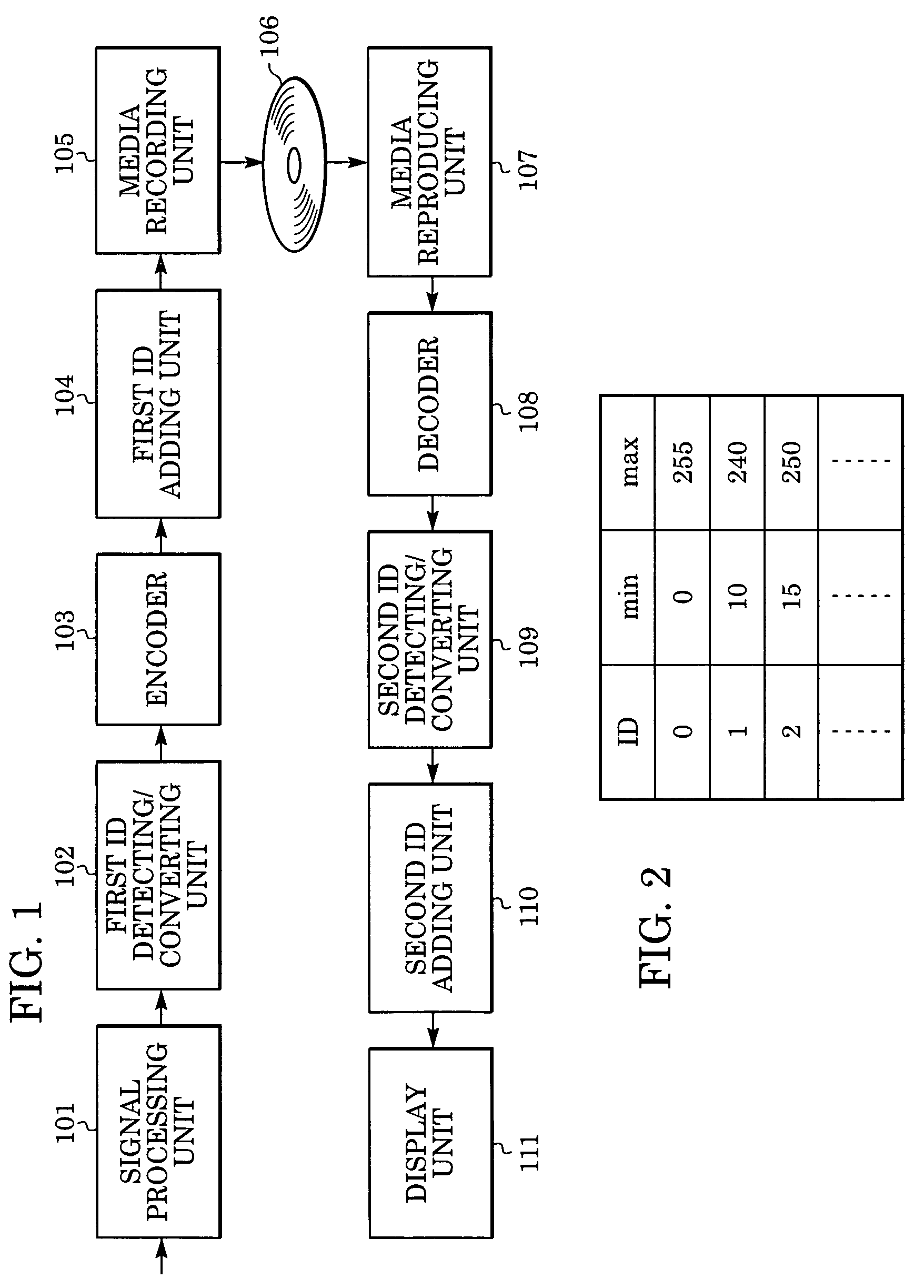
[0025]FIG. 1 is a block diagram of an image processing apparatus in a first embodiment of the present invention.

[0026] The image signal which should be recorded on recording media 106 is input into signal processing unit 101 from an external apparatus. The signal processing unit 101 performs a color conversion and filtering on the image signal. Known general color conversion and filtering techniques can be used and are thus not described herein. The image signal processed by the signal processing unit 101 is input into a first ID detecting / converting unit 102. The first ID detecting / converting unit 102 detects ID information which indicates the level range of the image signal processed by the signal processing unit 101. A level range of the image signal is determined based on the ID information. Then, the level range of the image signal is converted so that it may become the level range corresponding to a coding processing. The image signal which is input into the first ID detectin...

second embodiment

[0053] A second embodiment of the present invention is described below.

[0054]FIG. 8 is a block diagram of an image processing apparatus in a second embodiment of the present invention. Components of the second embodiment (shown in FIG. 8) that have the same function as components of the first embodiment (shown in FIG. 1 and described above) have the same reference number.

[0055] In the embodiment illustrated in FIG. 1, the level range of the image signal is discriminated by the ID information (described above). In this embodiment, the level information which indicates the white level and black level of the image signal is added to the image signal, and the level information is transmitted. The level range of the image signal is determined by the level information.

[0056] The image signal that should be recorded on recording medium 106 is input into signal processing unit 101 from an external apparatus. As described above, the signal processing unit 101 performs a color conversion (...


PUM


Abstract

There is provided an image processing apparatus including a converting unit for converting a level range of an input image signal into a predetermined level range, and an outputting unit for outputting the converted image signal and first identification information which indicates the predetermined level range, the first identification information being correlated with the converted image signal.

Description

BACKGROUND OF THE INVENTION [0001] 1. Field of the Invention [0002] The present invention relates to digital signal processing for a multiple-valued image signal. [0003] 2. Description of the Related Art [0004] In image transmission including a recording and reproducing of image data, the image data is compression-encoded in order to reduce the amount of data. The image data that is compressed-encoded may have a dynamic range that is different. [0005] For example, a digital transmission specification “REC656” is prescribed to use a range of 16-235 in a range of 0-255 using 8-bit image data. That is, in the digital transmission specification, a black level is set to 16 and a white level is set to 235. The 8-bit image data which is not based on this transmission specification has the dynamic range from 0 to 255. Also, an image input apparatus can set up the dynamic range using a manual. The image data which has various dynamic ranges as described above can exist together. [0006] In ca...

Claims


Application Information

Patent Timeline
Patent Type & Authority Applications(United States)
IPC IPC(8): H04N5/76H04N5/781H04N5/85H04N5/91H04N5/92H04N9/804H04N19/00H04N19/70
CPCH04N5/76H04N9/8047H04N9/8042H04N5/85
Inventor OWADA, MITSURU
Owner CANON KK
Why Eureka
Try Eureka