Connecting structure for power cord

a technology of connecting structure and power cord, which is applied in the direction of printed circuits, casings/cabinets/drawers, electrical apparatus casings/cabinets/drawers, etc., can solve the problems of copper wire bundle breaking, short circuit, and difficulty in soldering work

Inactive Publication Date: 2005-12-29
FUNAI ELECTRIC CO LTD
View PDF0 Cites 7 Cited by
  • Summary
  • Abstract
  • Description
  • Claims
  • Application Information

AI Technical Summary

Benefits of technology

[0011] The present invention has been made in view of the above described problems of the related art, and an object of the invention is to provide a connecting structure for an AC cord which can completely insulate two poles of two bundles of copper wires of the AC cord from each other, and can prevent the copper wires in the bundles which have been broken from getting in contact with each other, thereby to avoid occurrence of fire due to such contact.
[0013] By thus configuration, the bifurcated portions of the AC cord are completely separated and insulated from each other by the small wall part which is uprightly formed integrally on the case body. Therefore, it is possible to prevent the copper wires which have been broken from getting in contact with each other, thereby to avoid occurrence of fire due to such contact. Moreover, because the through hole formed in the AC cord adjacent to the bifurcated portions is fitted on the L-shaped locking piece at the upper end of the small wall part to be locked thereto, the AC cord will not be detached nor inclined, but can be safely held. Further, the cut groove in the circuit board is engaged with the small wall part, thus enabling the circuit board to be correctly positioned with respect to the case body.
[0015] By thus configuration, the bifurcated portions of the AC cord are completely separated and insulated from each other by the small wall part which is uprightly formed on the case body. Therefore, it is possible to prevent the copper wires which have been broken from getting in contact with each other, thereby to avoid occurrence of fire due to such contact. Moreover, the cut groove or hole in the circuit board is engaged with the small wall part, thus enabling the circuit board to be correctly positioned with respect to the case body.
[0019] Because the locking hooks of a pair of the leg portions of the small wall part are inserted into the locking holes which are formed in the case body formed of metal, the small wall part will not be detached nor inclined, and the AC cord can be safely insulated.
[0023] By thus configuration, the bifurcated portions of the AC cord can be engaged with the locking grooves of the locking projections on both the faces of the small wall part which is uprightly provided on the case body, the bifurcated portions of the AC cord can be prevented from being separated.

Problems solved by technology

It has been a problem that while physical loads are applied to these stripped areas, the bundle of the copper wires starts to be broken, and the AC cord makes a short circuit between the two poles, which may be a cause for fire.
However, this structure has had a problem that the soldering work has been difficult, because the lead wire 103 was unable to be soldered until it had been inserted into the insertion hole 104.
However, in this structure, it has been concerned that a short circuit may occur in case where some of the core wires 315 have been broken on their way.

Method used


Image

  • Connecting structure for power cord
  • Connecting structure for power cord
  • Connecting structure for power cord

Examples


first embodiment

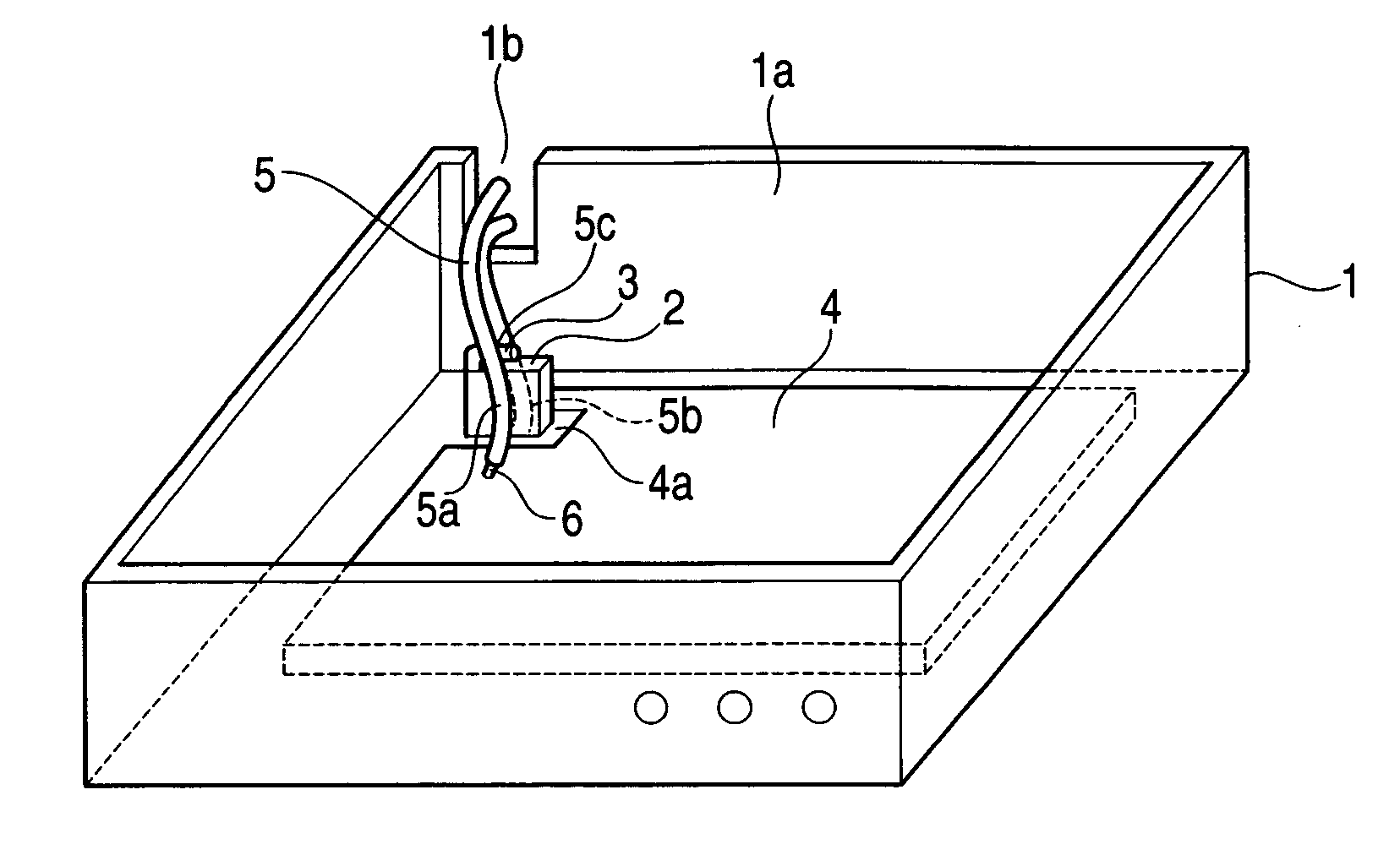
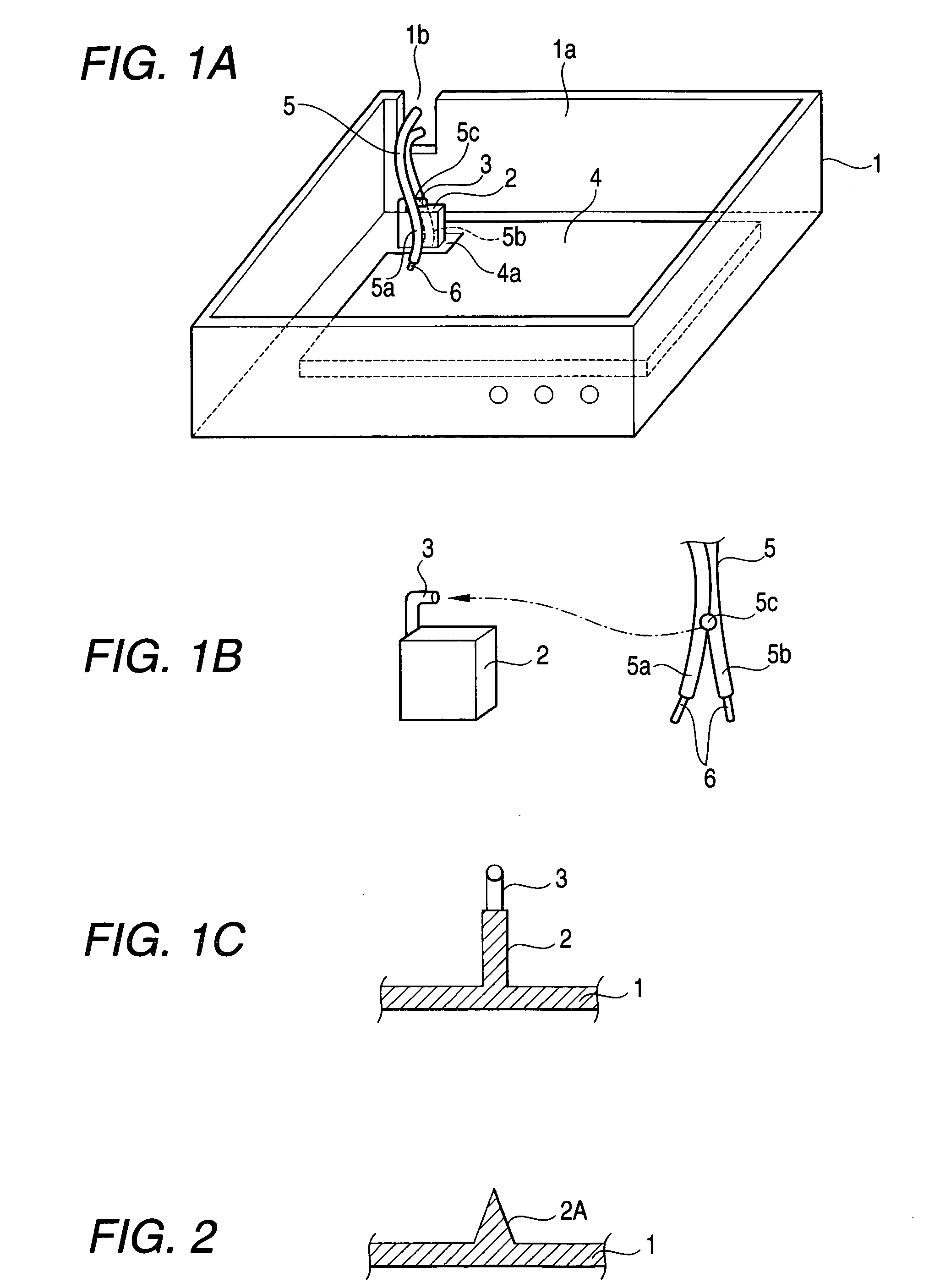
[0038]FIG. 1A is a perspective view of a general structure of connecting structure for the AC cord in a first embodiment according to the invention, FIG. 1B is an exploded perspective view of an essential part thereof, and FIG. 1C is a sectional view of the essential part.

[0039] In the connecting structure for the AC cord in this first embodiment, a case body 1 formed of synthetic resin has a small wall part 2 which is integrally formed at a determined position of the case body 1 so as to protrude upwardly. The small wall part 2 is provided with a locking piece 3 in a substantially L-shape, at an upper end thereof. A circuit board 4 is formed with a cut groove 4a at a position corresponding to the small wall part 2, and the small wall part 2 is inserted into the cut groove 4 in the circuit board 4 when the circuit board 4 is arranged inside the case body 1. Moreover, an AC cord 5 which has entered into the case body 1 through a slit 1b formed in a side wall 1a of the case body 1 is ...

second embodiment

[0041]FIG. 2 is a sectional view showing an essential part of the connecting structure for the AC cord in a

[0042] In the connecting structure for the AC cord in the second embodiment, the case body 1 is formed of synthetic resin, and the small wall part 2A is formed at a determined position of the case body 1 integrally and in a pointed shape directed upwardly, as shown in FIG. 2.

[0043] Therefore, according to this second embodiment, because the small wall part 2A is formed in a pointed shape, the bifurcated portions 5a, 5b of the AC cord 5 can be extended along inclination of the pointed shape of the small wall part 2A.

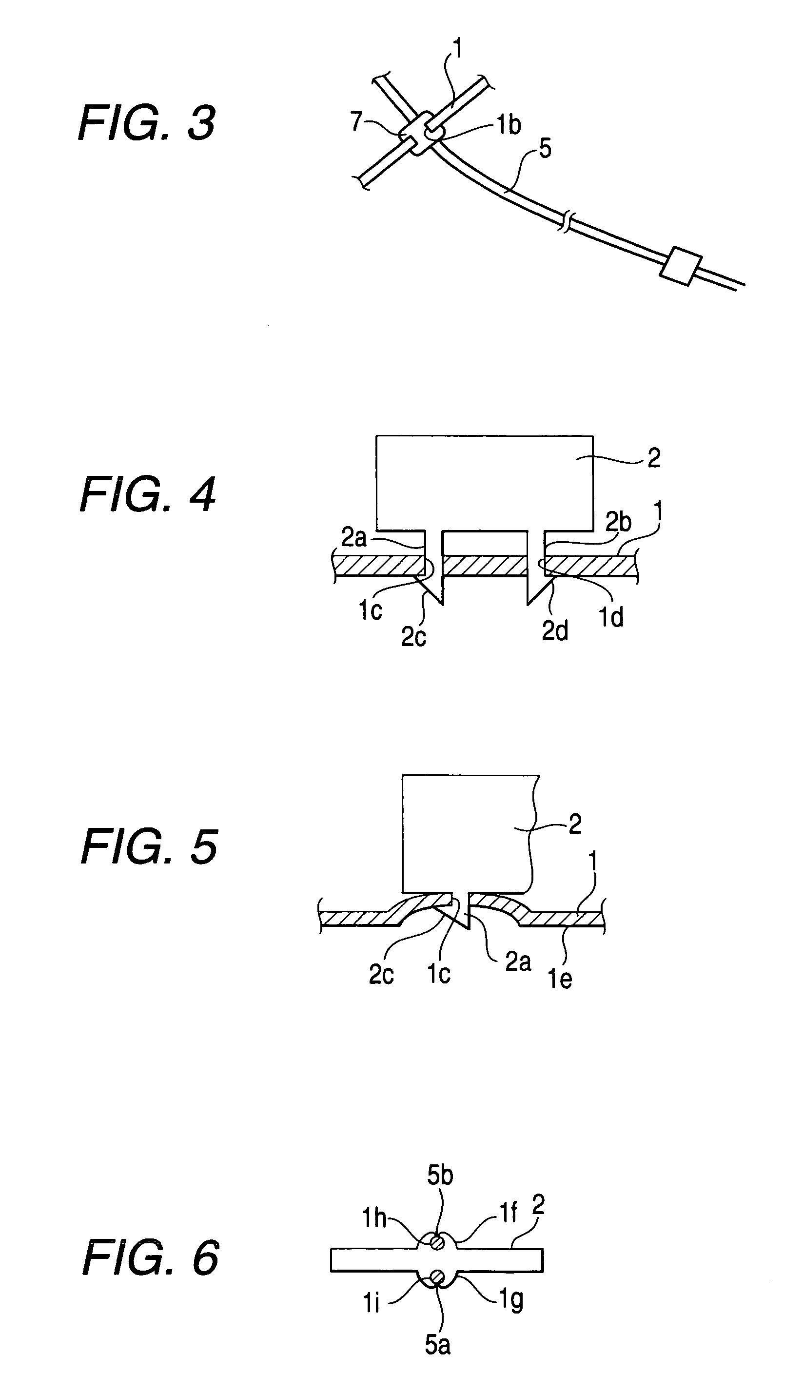
[0044]FIG. 3 is a plan view showing a part of a holding mechanism for the AC cord.

[0045] In this holding mechanism for the AC cord, a locking member 7 which is provided on a halfway of a shielded area of the AC cord 5 and has grooves on its outer periphery is inserted into the slit 1b of the case body 1, as shown in FIG. 3.

[0046] Therefore, by inserting the locki...

third embodiment

[0047]FIG. 4 is a sectional view showing an essential part of the connecting structure for the AC cord in a

[0048] In the connecting structure of the AC cord in the third embodiment, the case body 1 is formed of metal, and the small wall part 2 is provided with a pair of leg portions 2a, 2b, in a lower part thereof, as shown in FIG. 4. Locking hooks 2c, 2d are formed at lower ends of these leg portions 2a, 2b. The case body 1 is provided with locking holes 1c, 1d into which a pair of the leg portions 2a, 2b of the small wall part 2 are inserted, so that the locking hooks 2c, 2d can be locked to a lower face 1e of the case body 1.

[0049] Therefore, according to this third embodiment, because the locking hooks 2c, 2d of a pair of the leg portions 2a, 2b of the small wall part 2 are inserted into and locked to the locking holes 1c, 1d which are formed in the case body 1 formed of metal, the small wall part 2 will not be detached nor inclined, and the AC cord 5 can be safely insulated.


PUM


Abstract

A small wall part is formed at a determined position of a case body to protrude upwardly therefrom. The small wall part is provided with a locking piece at an upper end, and a circuit board is provided with a cut groove at a position corresponding to the small wall part. The small wall part is fitted into the cut groove when the circuit board is arranged inside the case body. A distal end of the AC cord which has entered into the case body through a slit formed in a side wall of the case body is divided into bifurcated portions, and the bifurcated portions are arranged to stride over the small wall part. The bundles at respective distal ends of the bifurcated portions are connected to a pattern of the circuit board.

Description

BACKGROUND OF THE INVENTION [0001] 1. Field of the Invention [0002] The present invention relates to a connecting structure for a power cord having a circuit board arranged inside a case body, the power cord being adapted to be connected to this circuit board. [0003] 2. Description of the Related Art [0004] In a conventional connecting structure for an AC cord of this type, a bundle of copper wires at a distal end of the AC cord is stripped in some areas of a soldered part between the AC cord and the circuit board, at a primary side of an electric power block of the circuit board. It has been a problem that while physical loads are applied to these stripped areas, the bundle of the copper wires starts to be broken, and the AC cord makes a short circuit between the two poles, which may be a cause for fire. [0005] A first example of the connecting structure in the related art is shown in FIGS. 7A and 7B. In this structure, as shown in FIGS. 7A, 7B, a bushing 101 has a lower face forme...

Claims


Application Information

Patent Timeline
Patent Type & Authority Applications(United States)
IPC IPC(8): H01R12/00H05K5/02
CPCH05K5/0247
Inventor MURAMATSU, AKIRA
Owner FUNAI ELECTRIC CO LTD
Why Eureka
Try Eureka