Engine subframe mounting arrangement

Active Publication Date: 2006-01-05
BLUE LEAF I P
View PDF19 Cites 3 Cited by
  • Summary
  • Abstract
  • Description
  • Claims
  • Application Information

AI Technical Summary

Benefits of technology

[0009] In a first embodiment of the present invention, a subframe arrangement for a mobile vehicle chassis assembly is configured to enhance isolation of the chassis assembly from the drive mechanism. The chassis assembly includes a front axle and a rear axle and a pair of elongated side supports interconnected therebetween. The first and second elongated frame side supports are each located on either side of a longitudinal axis of the chassis assembly.

Problems solved by technology

The chassis assembly transfers these torque forces to the subframe assembly, leading to wear and tear to the drive subframe assembly and drive mechanism.
In particular, these torque forces are known to crack welds attaching the subframe assembly with the chassis assembly.
A drawback of the Muller auxiliary frame is that the auxiliary frame employs an elongated support structure that allows the auxiliary frame to twist rather than float as a level, rigid subframe.
A drawback is that the Miura et al. subframe employs elastic support members that again allow the subframe to flex and twist rather than float as a level, rigid subframe.

Method used


Image

  • Engine subframe mounting arrangement
  • Engine subframe mounting arrangement
  • Engine subframe mounting arrangement

Examples


Embodiment Construction

[0019] A wide variety of vehicles could be constructed in accordance with the invention defined by the claims. Hence, while preferred embodiments of the invention will now be generally described with reference to a subframe arrangement in support of a drive unit associated with movement of a chassis assembly of a mobile vehicle in a direction of travel. The type of drive unit (e.g., hydraulic, pneumatic, mechanical, electrical, etc.) and combinations thereof can vary.

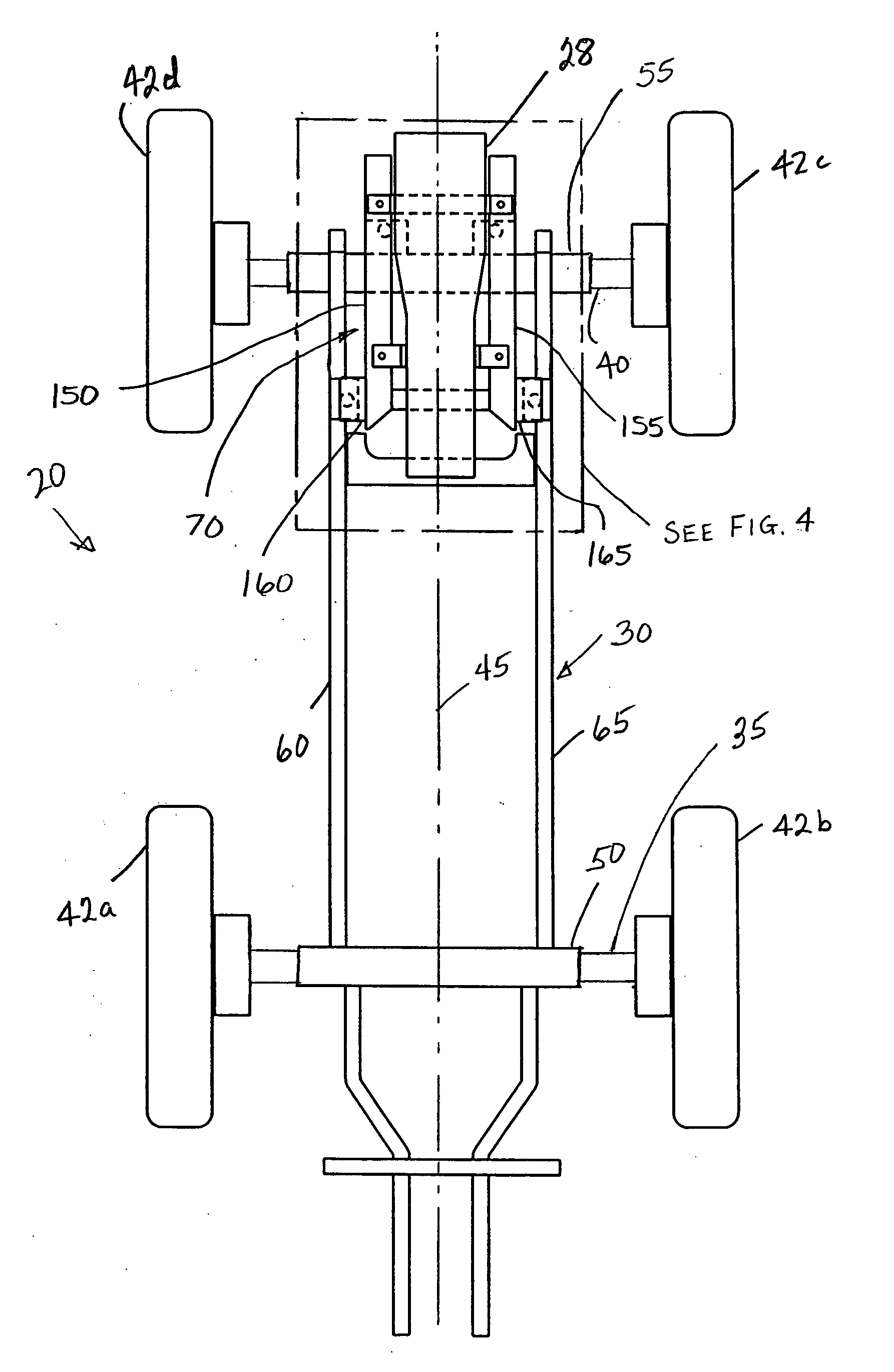
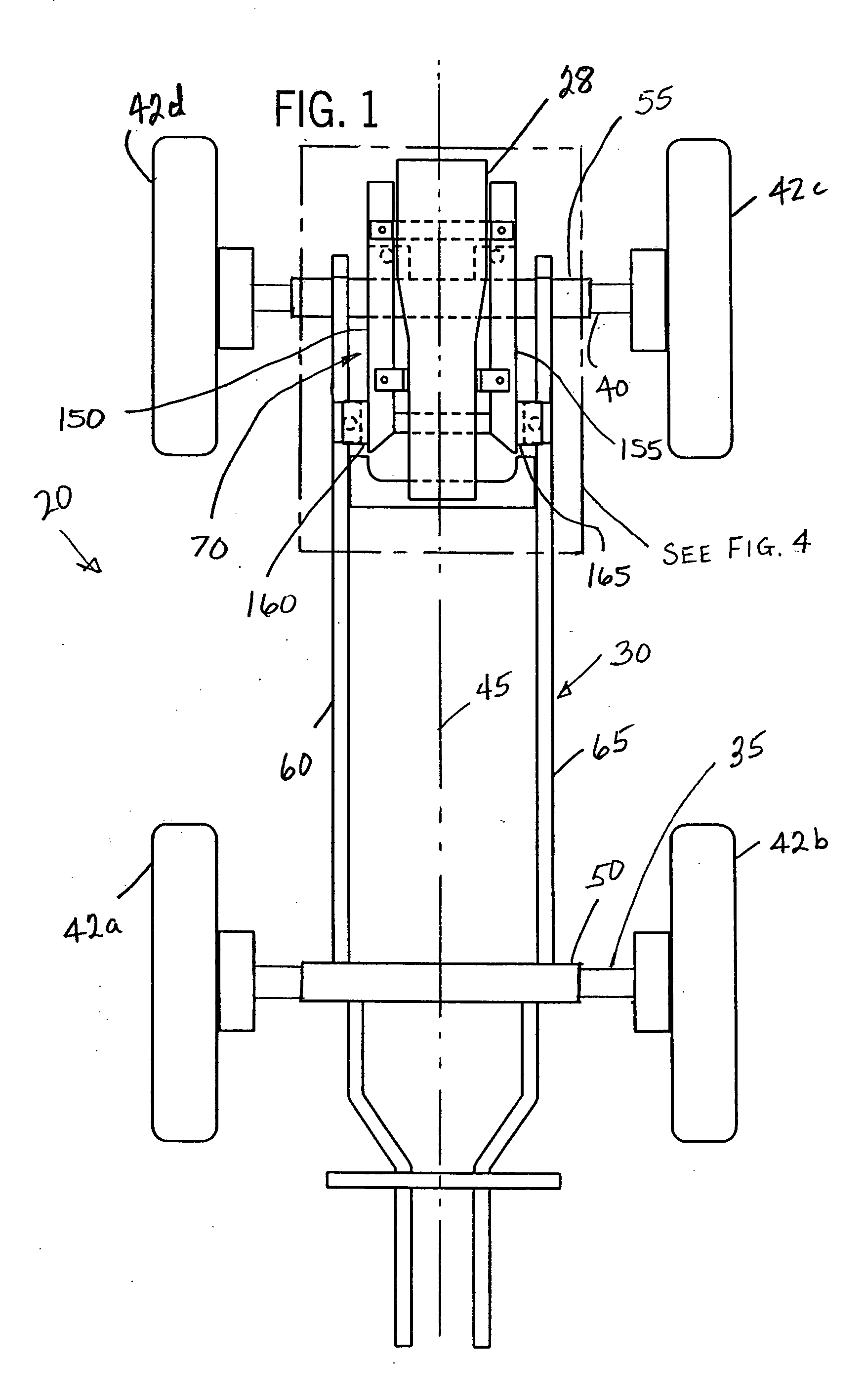
[0020]FIGS. 1 and 5 illustrate a mobile chassis assembly 20 having a preferred embodiment of a subframe arrangement 25 in accordance with the present invention. The subframe arrangement 25 is in support of a drive unit 28 of the mobile chassis assembly 20. A preferred embodiment of the mobile chassis assembly 20 as shown employs a frame 30 in support of a front axle 35, a rear axle 40, and associated wheel assemblies 42 a-d. A longitudinal axis 45 generally extends in the direction of travel of the chassis assembly 20....


PUM


Abstract

A subframe arrangement is configured for a mobile vehicle chassis assembly to enhance isolation of the subframe platform and drive mechanism from flex in the chassis assembly caused by dynamic forces associated with operation of the chassis assembly. The chassis assembly includes a frame having a front and a rear frame support, and a pair of elongated frame side supports interconnected therebetween. The subframe arrangement includes a subframe platform configured to receive the drive-unit, and a plurality of subframe mounting couplings operable to attach the subframe platform to the pair of elongated frame side supports. Each of the plurality of subframe mounting couplings is located along a generally isosceles triangular-shaped arrangement that enhances isolation of the subframe arrangement and attached drive unit.

Description

BACKGROUND OF THE INVENTION [0001] 1. Field of the Invention [0002] The invention relates to a vehicular chassis assembly and, more particularly, relates to a vehicular chassis assembly in combination with a subframe mounting arrangement configured to isolate a mounted drive unit from deflection and distortion associated with operation of the chassis assembly. [0003] 2. Discussion of the Related Art [0004] Large mobile vehicles generally employ a drive mechanism or unit configured to drive a chassis assembly. The vehicular chassis assembly typically includes a front axle and a rear axle driven by the drive mechanism, and a cradle or subframe assembly configured to receive the drive mechanism. Specifically, in regard to operation of large vehicles (e.g., agricultural applicators, etc.) over rough terrain, extreme torque forces are transferred from the front and rear axles to the chassis assembly. The chassis assembly transfers these torque forces to the subframe assembly, leading to ...

Claims


Application Information

Patent Timeline
IPC IPC(8): B60K5/12
CPCB62D21/11B60K5/12
Inventor REESE, SCOTT D.MOEN, RICHARD A.BASTIN, BRUCE G.LENT, KEVIN C.
Owner BLUE LEAF I P
Why Eureka
Try Eureka