Imaging apparatus and image processing method

a technology of image processing and image processing, applied in the field of image processing apparatus and image processing method, can solve the problems of partial morphing of a subject, insufficient implementation of conventional techniques, and inability to meet detailed requests for morphing by users

Inactive Publication Date: 2006-01-05
KYOCERA CORP
View PDF10 Cites 32 Cited by
  • Summary
  • Abstract
  • Description
  • Claims
  • Application Information

AI Technical Summary

Benefits of technology

[0009] In light of the above circumstances, an object of the present invention is to provide an imaging apparatus for performing image transformation of a created image, and a relevant image processing method, so as to implement users' detailed requests for image transformation by clearly showing the user target area(s) for image transformation.

Problems solved by technology

However, in the conventional morphing process using a marking, detailed requests from users for morphing cannot be satisfied.
That is, there are various requests for partial morphing of a subject, which are not sufficiently implemented by conventional techniques.

Method used


Image

  • Imaging apparatus and image processing method
  • Imaging apparatus and image processing method
  • Imaging apparatus and image processing method

Examples


first embodiment

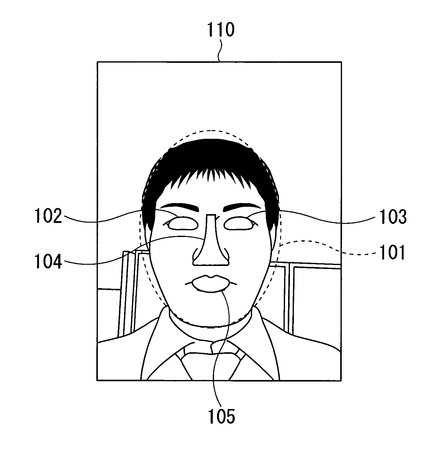
[0080]FIG. 9 shows an example of the transformed image in the The transformed image 120 in FIG. 9 is obtained by subjecting only the eyes of the subject, which is a human, to the morphing process so as to transform the eyes to the down-turned slant eyes. FIG. 10 shows the created image 121 as the original image for morphing.

[0081] When the user pushes the “store” key (here, the soft key 15c) in the transformed image confirmation screen P1-9, the main control section 111 stores the transformed image in the data folder section 14. The main control section 11 then displays a storage screen P1-111.

[0082] When the user pushes the OK key (here, the soft key 15b) in the transformed image confirmation screen P1-9, the main control section 111 displays a morphing preview screen P1-10 in which data of an animation image from the originally created image to the transformed image are reproduced. When the user pushes the “store” key (here, the soft key 15b) in the morphing preview screen P1-10...

second embodiment

[0097]FIG. 14 shows an example of the transformed image in the The transformed image 200 in FIG. 14 is obtained by the morphing process in which the face of a human as the subject in the created image 121 in FIG. 10 is transformed based on a synthetic target image 210 in FIG. 12.

[0098] When the user pushes the “store” key (here, the soft key 15c) in the transformed image confirmation screen P2-9, the main control section 11 stores the transformed image in the data folder section 14 and displays a storage screen P2-11.

[0099] When the user pushes the OK key (here, the soft key 15b) in the transformed image confirmation screen P2-9, the main control section 11 displays a morphing preview screen P2-10 in which data of an animation image from the originally created image to the transformed image are reproduced. When the user pushes the “store” key (here, the soft key 15b) in the morphing preview screen P2-10, the main control section 11 stores the animation data in the data folder sect...


PUM


Abstract

An imaging apparatus includes a photographing device for acquiring a created image; and a display device for showing a preview image of the created image. The apparatus may have a control device for superimposing a plurality of outlines on the preview image shown on the display device, and subjecting at least one of areas, which are included in the created image and are surrounded by the outlines in the preview image, to an image transformation process. Alternatively, the apparatus has a control device for superimposing an outline, which corresponds to a synthetic target image indicating a target image of transformation, on the preview image shown on the display device, and subjecting an area, which is included in the created image and is surrounded by the outline in the preview image, to an image transformation process performed based on the synthetic target image.

Description

BACKGROUND OF THE INVENTION [0001] 1. Field of the Invention [0002] The present invention relates to an imaging apparatus and an image processing method. [0003] Priority is claimed on Japanese Patent Application No. 2004-193142, filed Jun. 30, 2004, the content of which is incorporated herein by reference. [0004] 2. Description of Related Art [0005] As a conventional image transformation processing technique, a morphing method is known, which is used for generating an animation image in computer graphics. In the morphing method, a still image A is associated with another still image B, and feature points are identified in each still image, and transition from the feature points of the still image A to the feature points of the still image B over a period of time is estimated. Coordinates or color data for the transition route are then determined, thereby generating animation image data for an animation, or extracting a still image in the route of the transition, as a transformed ima...

Claims


Application Information

Patent Timeline
Patent Type & Authority Applications(United States)
IPC IPC(8): G09G5/00
CPCG06T11/60G06T2210/44G06T3/0093
Inventor HONDA, NATSUHITO
Owner KYOCERA CORP
Why Eureka
Try Eureka