Projector-camera system with laser pointers

a laser pointer and projector technology, applied in the field of projectors, can solve the problems of raising a new problem, unable to treat the arrangement of laser pointers as a pinhole projection, and even more difficult problems when projecting onto textured surfaces

Inactive Publication Date: 2006-01-05
MITSUBISHI ELECTRIC RES LAB INC
View PDF5 Cites 26 Cited by
  • Summary
  • Abstract
  • Description
  • Claims
  • Application Information

AI Technical Summary

Problems solved by technology

The problem is even more difficult when projecting onto a textured surface, rather than a homogeneous surface.
This raises a new problem.
Therefore, the arrangement with laser pointers cannot be treated as a pinhole projection.

Method used


Image

  • Projector-camera system with laser pointers
  • Projector-camera system with laser pointers
  • Projector-camera system with laser pointers

Examples


Embodiment Construction

[0018] System Structure

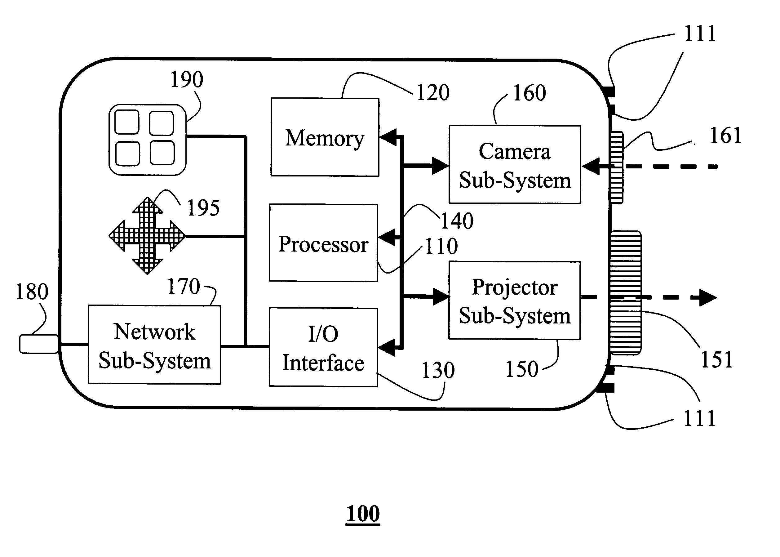
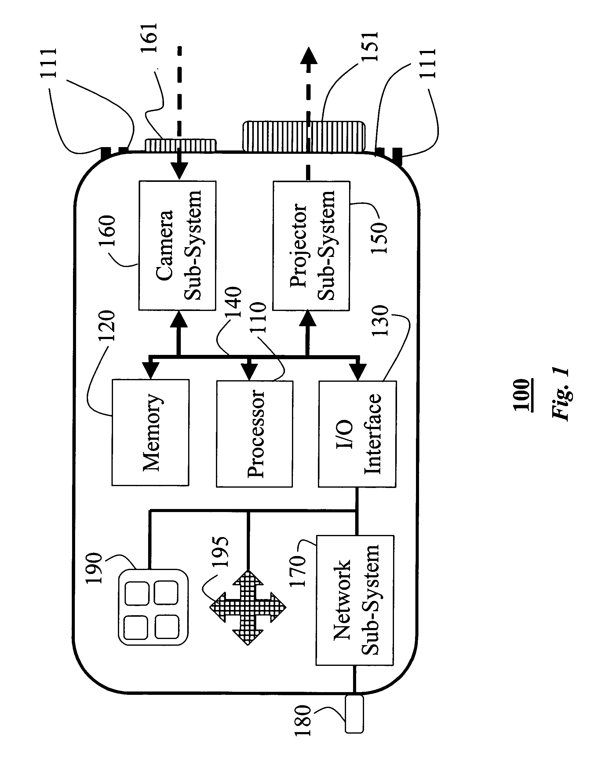
[0019]FIG. 1 shows a projector-camera system 100 according to our invention. It should be noted that the system 100 can be used in both front and rear projection modes, and alone or in a cooperative combination with other similar projectors.

[0020] Our system 100 includes a microprocessor 110, a memory 120, and an I / O interface 130 connected by buses 140, generally a processing unit. The processing unit is conventional in its electronic structure, but unconventional in its operation when performing the method steps described herein.

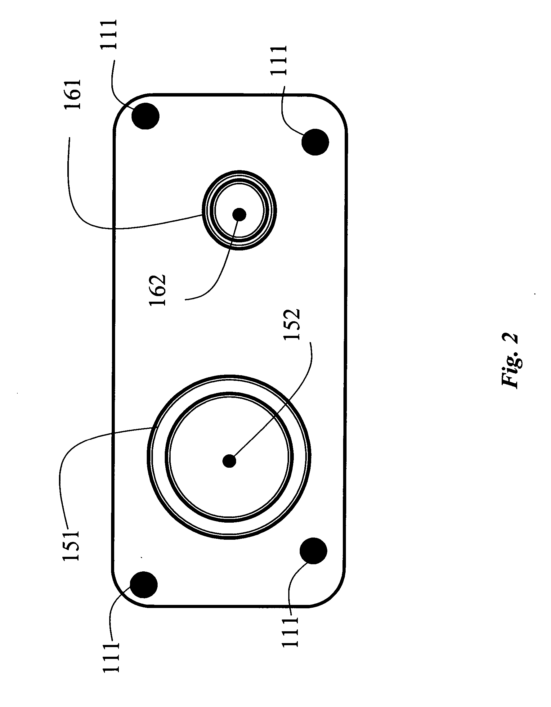
[0021] The system 100 also includes a projector sub-system 150 for displaying output images, and a camera sub-system 160 for acquiring input images. The projector sub-system 150 includes a projector lens 151 with a projector focal point 152, and the camera sub-system 160 includes a camera lens 161 and a camera focal point 162.

[0022] As shown in FIG. 2, laser pointers 111, e.g., four, are also attached to the projector system 100....


PUM


Abstract

A rigidly-coupled projector-camera system is augmented with laser pointers. The projector-camera system and lasers can be used to determine homography between the projector and a display surface, so that a projection of any desired geometry can be made on the display surface.

Description

FIELD OF THE INVENTION [0001] This invention relates generally to projectors, and more particularly to calibrating projectors with cameras and laser pointers. BACKGROUND OF THE INVENTION [0002] A projector with rigidly attached camera can be used as a handheld projection system, U.S. patent application Ser. No. 10 / 394,314 “Geometrically Aware Projector,” filed by Raskar et al., on Mar. 21, 2003, U.S. patent application Ser. No. 10 / 012,930 “Method for Calibrating a Projector with a Camera,” filed by Raskar et al. on Dec. 10, 2001, and U.S. patent application Ser. No. 10 / 394,315 “Projector as an input and output device,” filed by Beardsley et al., on Mar. 21, 2003, all incorporated herein by reference, and Raskar et al., “iLamps: Geometrically aware self-configuring projectors, SIGGRAPH Proceedings, 2003. [0003] As the projector projects an output image on a display surface, the camera acquires an input image of the output image. The input image can be used to determine a pose of the ...

Claims


Application Information

Patent Timeline
Patent Type & Authority Applications(United States)
IPC IPC(8): G03B21/00
CPCG03B21/14G03B21/26H04N9/3194H04N9/3185H04N5/74G03B17/54
Inventor BEARDSLEY, PAUL A.VAN BAAR, JEROENRASKAR, RAMESH
Owner MITSUBISHI ELECTRIC RES LAB INC
Why Eureka
Try Eureka