Closed-loop compensation of streaks by ros intensity variation

Active Publication Date: 2006-01-05
XEROX CORP
View PDF10 Cites 48 Cited by
  • Summary
  • Abstract
  • Description
  • Claims
  • Application Information

AI Technical Summary

Problems solved by technology

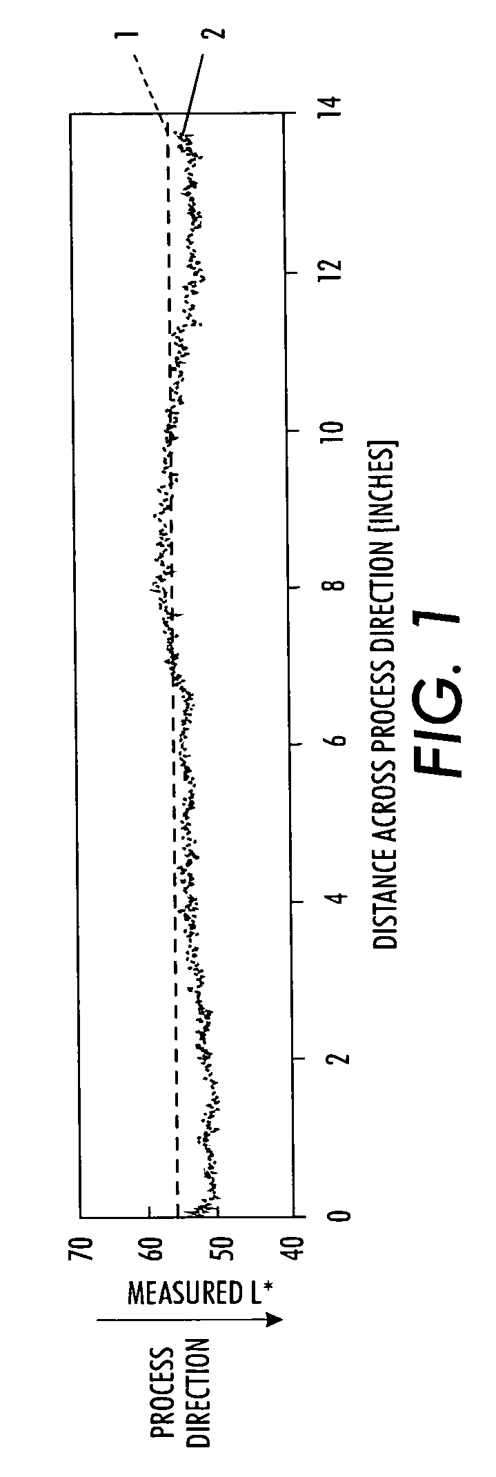
Although a xerographic system usually produces a faithful reproduction of the original image, defects in the subsystems of the xerographic may give rise to visible streaks in the reproduced image.
Streaks are primarily one-dimensional defects in an image that run parallel to the process or slow-scan direction.
Streaks are caused by “non-ideal” responses of xerographic components in the marking engine.
For example, these streaks may be caused by contamination of a wire module in a hybrid scavengeless development subsystem, contamination of a charging device or grid, scratches in the photoreceptor, differential abrasions of the photoreceptor, and raster output scanning device spot-size or intensity variations.
Another frequent source of streaks is the non-uniformity of the raster output scanning device itself.
This non-uniformity occurs because of problems in meeting the tight requirements

Method used


Image

  • Closed-loop compensation of streaks by ros intensity variation
  • Closed-loop compensation of streaks by ros intensity variation
  • Closed-loop compensation of streaks by ros intensity variation

Examples


Embodiment Construction

[0030] The present invention will be described in connection with specific embodiments; however, it will be understood that there is no intent to limit the present invention to the embodiments described herein. On the contrary, the intent is to cover all alternatives, modifications, and equivalents as may be included within the spirit and scope of the present invention as defined by the appended claims.

[0031] For a general understanding of the present invention, reference is made to the drawings. In the drawings, like reference have been used throughout to designate identical or equivalent elements. It is also noted that the various drawings illustrating the present invention are not drawn to scale and that certain regions have been purposely drawn disproportionately so that the features and concepts of the present invention could be properly illustrated.

[0032] In the various descriptions given above and below, the term fast-scan direction or cross-process direction refers to the ...


PUM


Abstract

A method and system compensates for streak defects in an image formed using a raster output scanning device. A reflectance profile is generated from an image generated by the raster output scanning device. Thereafter, a difference profile is determined. The difference profile is determined based upon the generated reflectance profile and a uniform profile. A compensation profile is generated based on the determined difference profile. The compensation profile represents a change in an intensity profile for the raster output scanning device.

Description

FIELD OF THE PRESENT INVENTION [0001] The present invention relates to the field of digital imaging and, more particularly, to a system and method compensating for streaks and other image artifacts that appear on a printed image and which run parallel to the printer's process direction by using a raster output scanner as the compensation actuator. BACKGROUND OF THE PRESENT INVENTION [0002] Image reproduction systems provide a means to reproduce images in a variety of formats. An example of an image reproduction system is a xerographic (“dry writing”) system. In this system, a latent image of electrical charges is formed on a photosensitive film. The location of the electrical charge forming the latent image is usually optically controlled. More specifically, in a digital xerographic system, the formation of the latent image is controlled by a raster output scanning device, usually a laser or LED source. [0003] Although a xerographic system usually produces a faithful reproduction of...

Claims


Application Information

Patent Timeline
IPC IPC(8): G06K15/00H04N1/409G06T5/00
CPCH04N1/4015
Inventor VIASSOLO, DANIEL E.MIZES, HOWARD A.UPDEGRAFF, SHAWN P.
Owner XEROX CORP
Why Eureka
Try Eureka