Active termination control

Inactive Publication Date: 2006-01-05
ROUND ROCK RES LLC
View PDF36 Cites 112 Cited by
  • Summary
  • Abstract
  • Description
  • Claims
  • Application Information

AI Technical Summary

Problems solved by technology

However, external resistors for all the signal lines located on system boards use a large amount of area on these boards.

Method used


Image

  • Active termination control
  • Active termination control
  • Active termination control

Examples


Embodiment Construction

[0021] In the following detailed description of the preferred embodiments, reference is made to the accompanying drawings which form a part hereof, and in which is shown by way of illustration, specific embodiments in which the inventions may be practiced. These embodiments are described in sufficient detail to enable those skilled in the art to practice the invention, and it is to be understood that other embodiments may be utilized and that process, electrical, or mechanical changes may be made without departing from the scope of the present invention. The following detailed description is, therefore, not to be taken in a limiting sense, and the scope of the present invention is defined only by the appended claims and their equivalents.

System

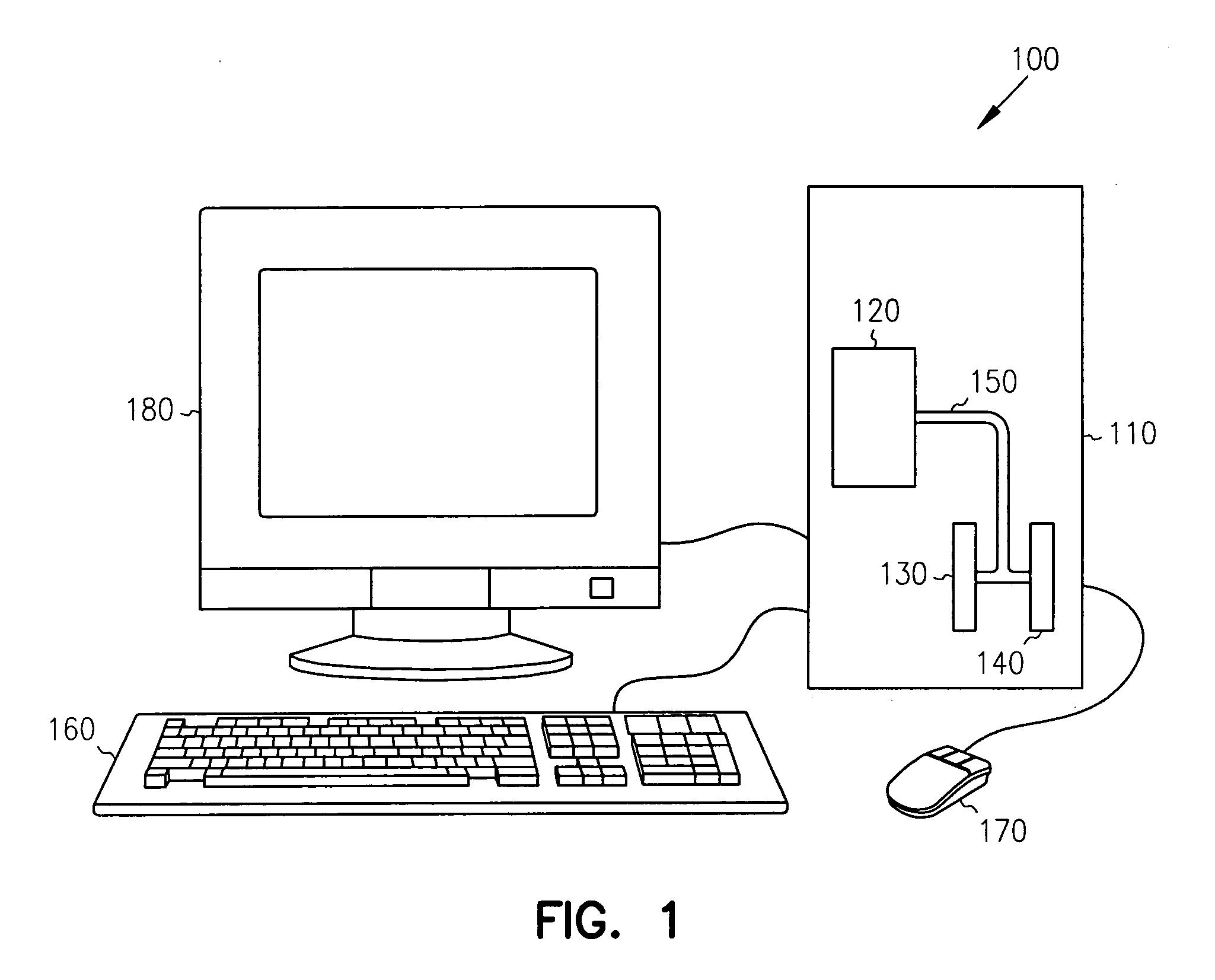
[0022]FIG. 1 shows an embodiment of a information handling system 100 including a computer system 110 having a controller 120 coupled to memory modules 130, 140, in accordance with the teachings of the present invention. Controller 120 is c...


PUM


Abstract

A method and apparatus are provided for active termination control in a memory by an module register providing an active termination control signal to the memory. The module register monitors a system command bus for read and write commands. In response to detecting a read or write command, the module register generates an active termination control signal to the memory. The memory turns on active termination based on information programmed into one or more mode registers of the memory. The memory maintains the active termination in an on state for a predetermined time based on information programmed into one or more mode registers of the memory.

Description

RELATED APPLICATIONS [0001] The present application is a divisional of U.S. application Ser. No. 10 / 383,939, filed Mar. 7, 2003; which claims priority to U.S. Provisional Application No. 60 / 427,917, filed Nov. 20, 2002; each of which is incorporated herein by reference.FIELD OF THE INVENTION [0002] The present invention relates to memory devices. In particular it relates to active termination control following read and write commands in memory devices. BACKGROUND OF THE INVENTION [0003] Many electronic systems employ controllers and memory devices that send information back and forth among each other. Typically, the information is transmitted on one or more system buses. These buses act as transmission lines. Consequently, these buses require designs that consider signal reflections associated with devices coupled to a transmission line. Typically, transmission lines are terminated using a resistor coupled between the transmission line and a power supply node. [0004] For electronic ...

Claims


Application Information

Patent Timeline
Patent Type & Authority Applications(United States)
IPC IPC(8): G11C7/00G06F13/40
CPCG06F13/4086G06F12/00G06F13/00
Inventor JANZEN, JEFFERY W.
Owner ROUND ROCK RES LLC
Why Eureka
Try Eureka