Removable garment protective assembly

a protective assembly and removable technology, applied in the field of protective clothing, can solve the problems of joint injuries, limiting mobility, tight elastic straps, etc., and achieve the effect of convenient removal and replacemen

Active Publication Date: 2006-01-12
LINEWEIGHT
View PDF7 Cites 41 Cited by
  • Summary
  • Abstract
  • Description
  • Claims
  • Application Information

AI Technical Summary

Benefits of technology

[0010] It is an object of the present invention to provide a protective pad assembly for a garment which protects the garment and the wearer from abrasion and impact.
[0011] It is another...

Problems solved by technology

Moreover, it is sometimes necessary to assume these positions rapidly or unexpectedly.
Certain sporting and leisure activities can also lead to joint injuries if precautions are not taken.
However, the tight elastic straps can be uncomfortable or can limit mobility.
Moreover, the close-fitting pads can be especially hot during extended wear.
In addition, the independent pads can be difficult to combine with other necessary garments, such as coveralls, fatigues, or jumpsuits, as the padding may, when used in combination with such clothing, restrict movement and ventilation and ...

Method used


Image

  • Removable garment protective assembly
  • Removable garment protective assembly
  • Removable garment protective assembly

Examples


Embodiment Construction

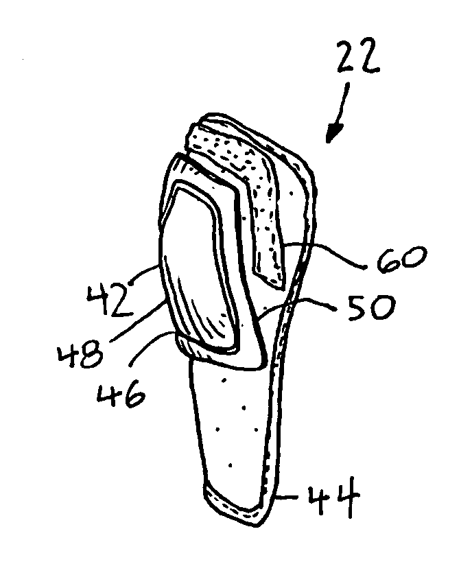
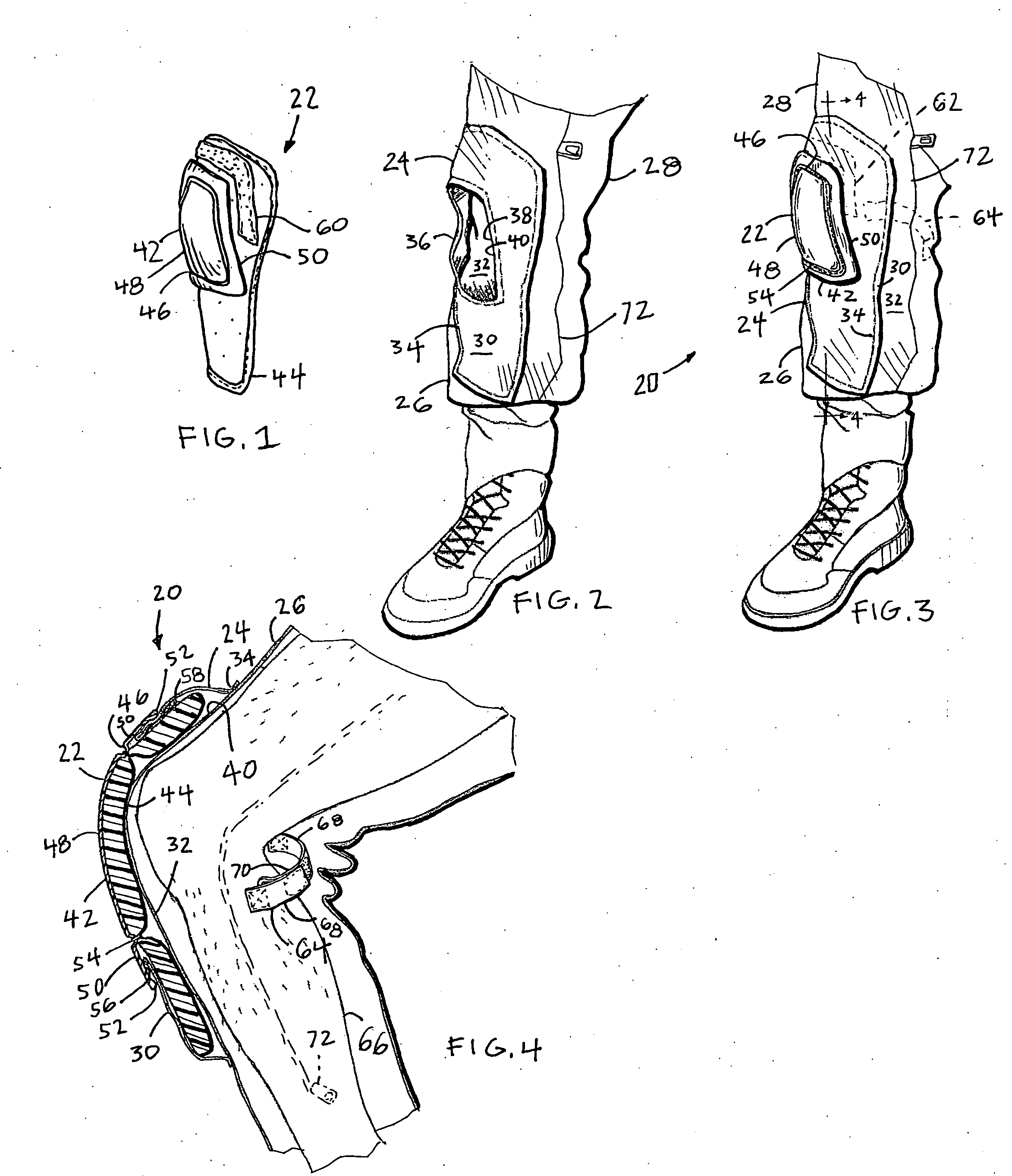
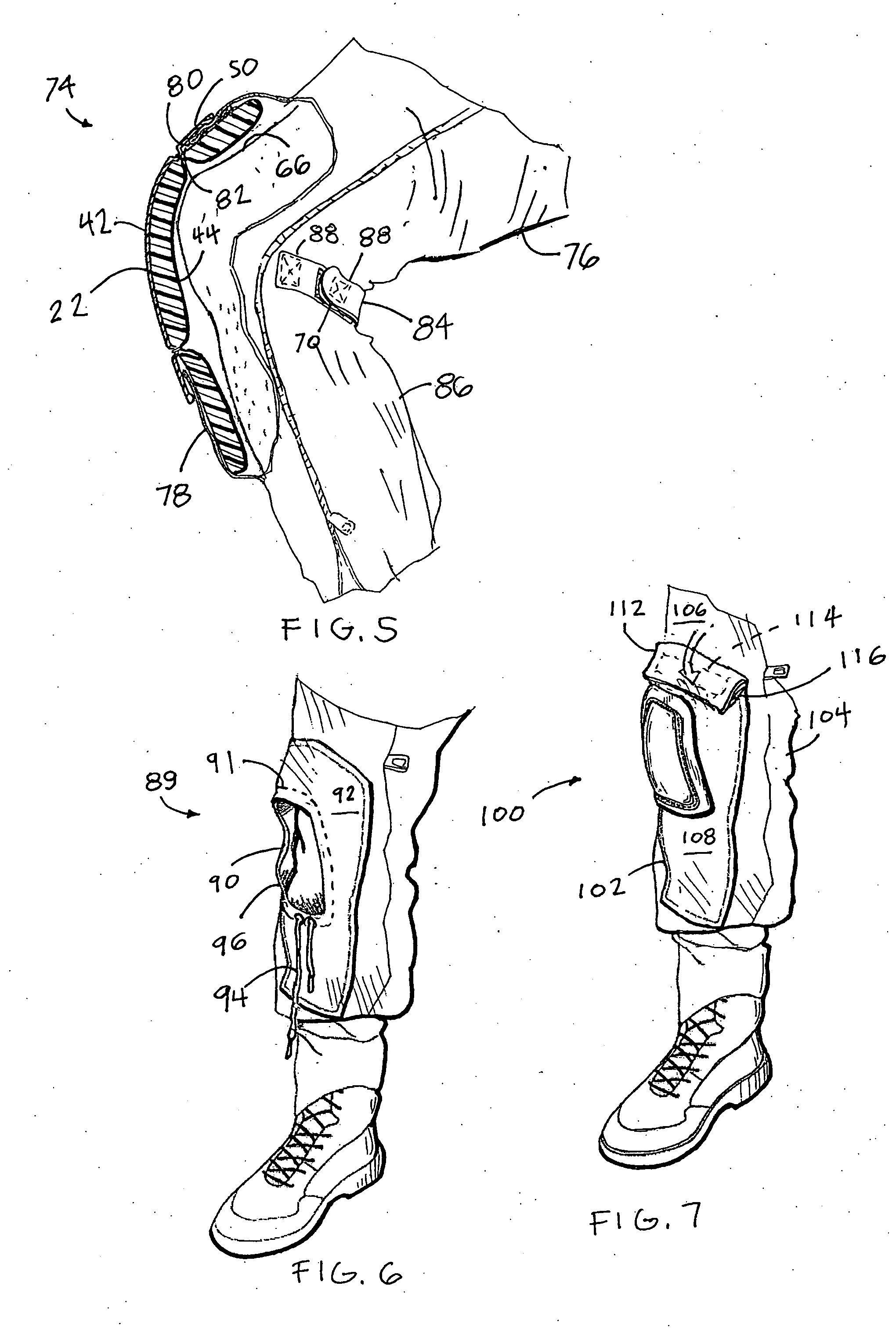
[0023] Referring more particularly to FIGS. 1-10, wherein like numbers refer to similar parts, a protective pad assembly 20 is shown in FIGS. 1-4. The protective pad assembly 20 is comprised of a protective element 22 shown in FIG. 1, and a pocket 24 formed on a pants leg 26 of a garment 28, for example a soldier's fatigues. The pocket 24 is accessible through a central opening 36, and in a first embodiment is not open at the top or sides as in a common pocket. As shown in FIG. 2, the pocket 24 is defined between a fabric front layer 30 and a frontwardly facing fabric substrate 32 of the garment 28. The protective pad assembly illustrated is a knee pad assembly, but a similar arrangement for an elbow or other body area pad may be provided.

[0024] The front layer 30 is connected to the garment substrate 32 at an outer peripheral seam 34, formed, for example, by stitching. A central opening 36 is defined in the front layer 30 which has an inner periphery 38 which may be finished by a ...


PUM


Abstract

A garment has a pants leg with a front layer stitched along an outer peripheral seam to the pants leg to form a pocket with an interior cavity. The front layer has a central opening spaced from the outer peripheral seam and defined by an inner periphery. A protective insert, which may be formed of foam, and which is larger than the central opening is removably positionable within the pocket. A stiff cap formed of a material such as SANTOPRENE® thermoplastic elastomer, is stitched to the insert. The cap has a flange which projects outwardly from a central region around a line of attachment. The central region is no larger than the pocket central opening. The insert is removably receivable within the pocket such that the inner periphery of the front layer is engaged between the stiff cap flange and the insert.

Description

STATEMENT AS TO RIGHTS TO INVENTIONS MADE UNDER FEDERALLY SPONSORED RESEARCH AND DEVELOPMENT [0001] The U.S. Government has a paid-up license in this invention and the right in limited circumstances to require the patent owner to license others on reasonable terms as provided for by the terms of contract No. DAAD 16-01-C-0061 awarded by the US Army Robert Morris Acquisition Natick Contracting Division of the United StatesCROSS REFERENCES TO RELATED APPLICATIONS [0002] Not applicable. BACKGROUND OF THE INVENTION [0003] The present invention relates to protective clothing in general, and more particularly to garments which incorporate pads for protection of the wearer's joints such as elbows and knees. [0004] There are many activities which require practitioners to take on cramped or reduced postures, such as crouching, crawling or lying prone, either momentarily or for extended periods. Moreover, it is sometimes necessary to assume these positions rapidly or unexpectedly. Kneeling an...

Claims


Application Information

Patent Timeline
IPC IPC(8): A41D13/00
CPCA41D13/065A41D13/0575
Inventor CRYE, CALEB CLARKFEHLBERG, ERIC OWENTHOMPSON, GREGG M.
Owner LINEWEIGHT
Why Eureka
Try Eureka