Impact test apparatus and impact test method

a test apparatus and test method technology, applied in the direction of instruments, material analysis, material strength using single impulsive force, etc., can solve the problems of difficult to evaluate the stress-strain characteristic of the test piece, the difficulty of evaluating the impact force applied to the test piece, and the difficulty of evaluating the impact absorbing material

Inactive Publication Date: 2006-01-12
NITTO DENKO CORP
View PDF13 Cites 34 Cited by
  • Summary
  • Abstract
  • Description
  • Claims
  • Application Information

AI Technical Summary

Benefits of technology

[0011] According to another aspect of the invention, there is provided an impact test method comprising the steps of: holding a test piece at an arbitrary holding force by a holding device; applying an impact force to the test piece held at the holding step by an impact applying device; sensing the impact force applied to the test piece at the impact applying step by an impact force sensing device and of detecting a displacement of the test piece when the impact force sensing device senses the impact force by a displacement detecting device; and outputting impact stress-strain characteristic information expressing a relationship between an impact stress and a strain corresponding to the impact stress of the test piece on the basis of the impact force and the displacement, which are sensed and detected at the detecting step, by an output device.
[0012] In the above-described impact test method, at a holding step, a test piece is held at an arbitrary holding force, and at an impact applying step an impact force can be applied to the test piece. Moreover, at a detecting step, the impact force applied to the test piece is sensed and the displacement of the test piece when the impact force is sensed is detected. Then, at an output step, impact stress-strain characteristic information expressing the relationship between an impact stress and a strain to the impact stress of the test piece can be obtained on the basis of the sensed impact force and the detected displacement.
[0013] Further, according to another aspect of the invention, there is provided an impact test method comprising the steps of: applying an impact force by an impact applying device in a state where a test piece is not set in a holding device; sensing the impact force at the first impact applying step by an impact force sensing device; holding the test piece at an arbitrary force by the holding device; applying an impact force to the test piece held at the holding step by the impact applying device; sensing the impact force applied to the test piece at the second impact applying step by the impact force sensing device; and outputting an impact absorption rate of the test piece by dividing an impact force, which is found by subtracting the impact force sensed at the second sensing step from the impact force sensed at the first sensing step, by the impact force sensed at the first sensing step to find an impact absorption rate.
[0014] In the above-described impact test method, first, at the first sensing step, an impact force is sensed which is applied by the impact applying device in a state where a test piece is not set in a holding device; next, a test piece is held at an arbitrary holding force by the holding device, and then at the second sensing step an impact force applied to the test piece by the impact force applying device is sensed. Then, an impact force, which is obtained by subtracting the impact force sensed at the second sensing step from the impact force sensed at the first sensing step, is divided by the impact force sensed at the first sensing step, whereby the impact absorption rate of the test piece can be obtained.

Problems solved by technology

Hence, it is difficult to evaluate an impact force applied to the test piece and an impact stress-strain characteristic of the test piece when the impact force is applied to the test piece.
Hence, it becomes difficult to evaluate the impact absorbing materials by the conventional impact tests or repulsion elasticity test on the same basis.

Method used


Image

  • Impact test apparatus and impact test method
  • Impact test apparatus and impact test method
  • Impact test apparatus and impact test method

Examples


embodiment 1

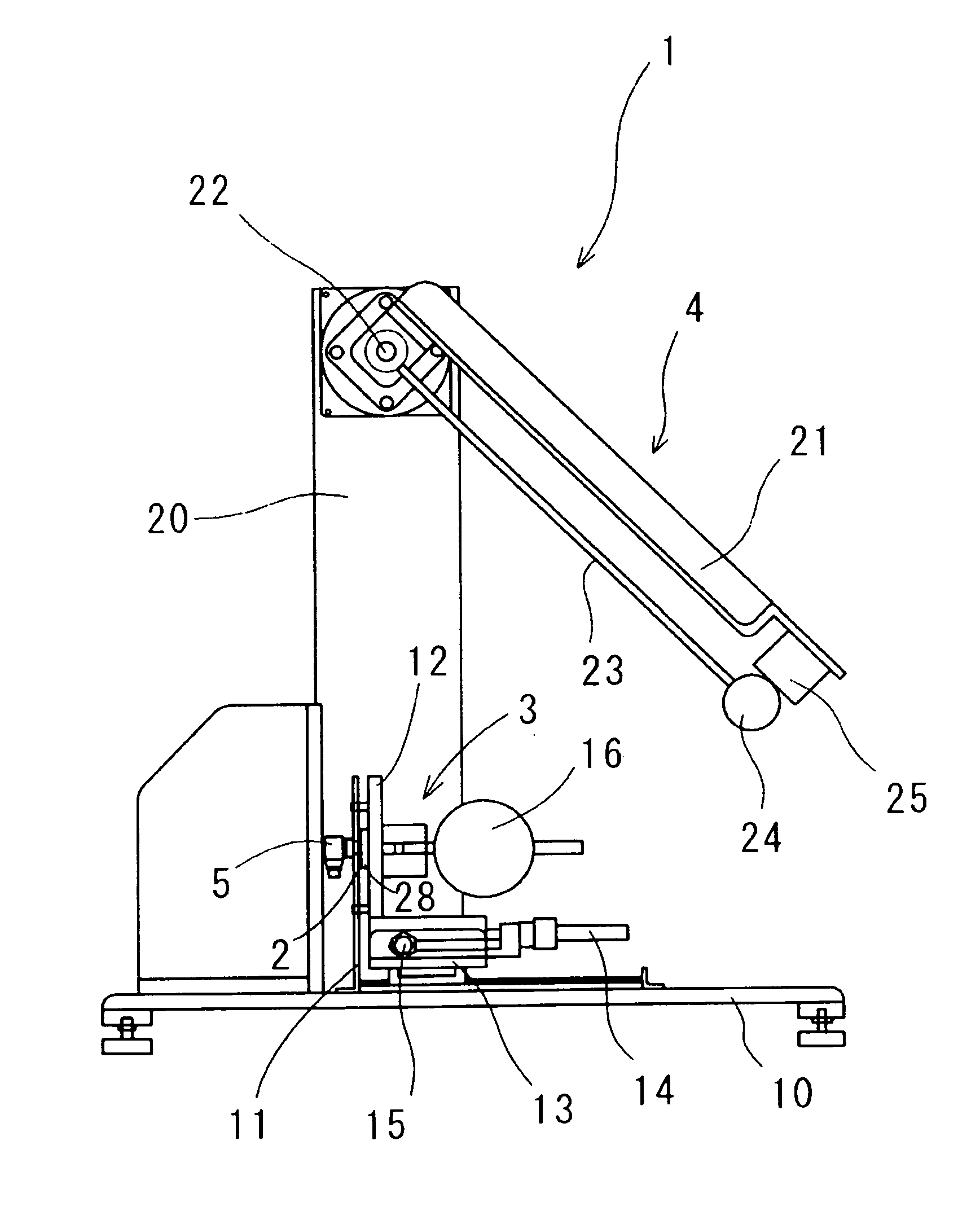
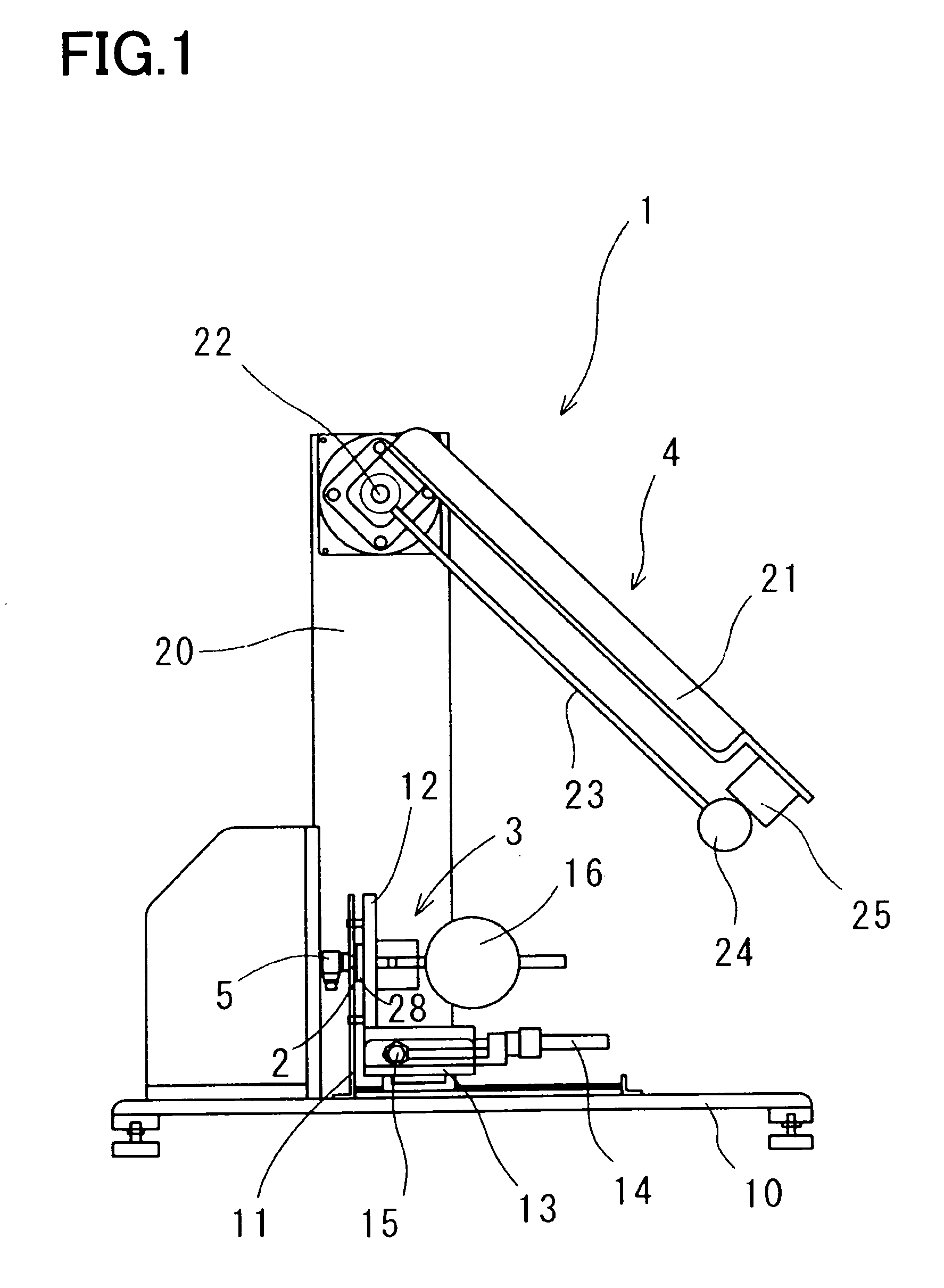
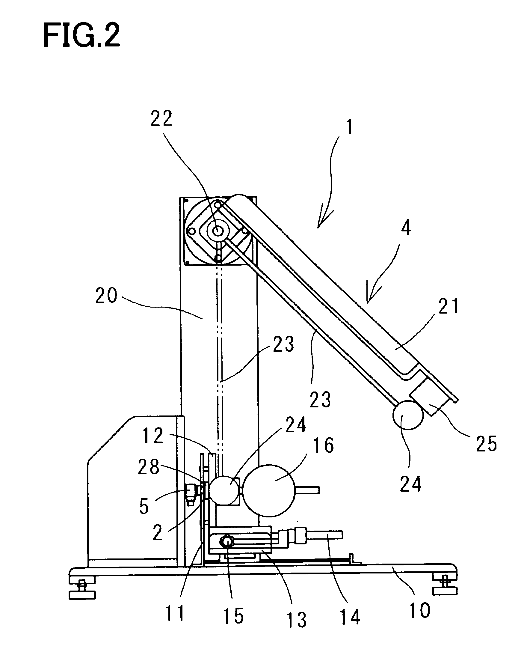
[0028] First, the schematic construction of an impact test apparatus in a first will be described with reference to FIGS. 1 to 4.

[0029] As shown in FIGS. 1 to 4, an impact test apparatus 1 in the first embodiment is constructed of: a holding device 3 for holding a test piece 2 at an arbitrary force; an impact applying device 4 for applying an impact stress to the test piece 2; a force sensor 5 as an impact force sensing device for sensing an impact force applied to the test piece 2 by the impact applying device 4; a high-speed camera 6 as a displacement detecting device for detecting the displacement of the test piece when the impact applying device 4 applies an impact force to the test piece 2; and an output device 7 for synchronizing a signal from the force sensor 5 with a signal from the high-speed camera 6 and outputting an impact stress-strain characteristic curve as impact stress-strain characteristic information expressing the relationship between an impact stress of the tes...

embodiment 2

[0053] Next, the schematic construction of an impact test apparatus in a second embodiment will be described with reference to FIGS. 7 to 9. Here, in the following description, the same reference symbols as in the construction or the like of the impact test apparatus 1 in the first embodiment shown in FIGS. 1 to 4 denote the same or equivalent parts as in the construction or the like of the impact test apparatus 1 in the first embodiment.

[0054] The schematic construction and control construction of an impact test apparatus in the second embodiment are nearly equal to those of the impact test apparatus 1 in the first embodiment.

[0055] However, as shown in FIGS. 7 to 9, an impact test apparatus 51 in the second embodiment is different from the construction of the impact test apparatus 1 in the first embodiment in that the holding device 3 having the force sensor 5 fixed thereto and the impact applying device 4, which construct the impact test apparatus 1 in the first embodiment, are...

embodiment 3

[0084] As shown in FIG. 11, in place of measuring the displacement of the test piece 2 by the use of the above-described high-speed camera 6, for example, an acceleration sensor 81 is fixed in a position close to a portion where the hammer 24 is brought into collision with the supporting plate 28 and an acceleration when the hammer 24 is brought into collision with the supporting plate 28 is integrated twice. With this, the displacement of the test piece 2 can be also found.


PUM

PropertyMeasurementUnit
humidityaaaaaaaaaa
temperaturesaaaaaaaaaa

Abstract

An impact test apparatus includes a holding device for holding a test piece at an arbitrary holding force, an impact applying device for applying an impact force to the test piece held by the holding device, a force sensor for sensing the impact force applied to the test piece by the impact applying device, a high-speed camera for detecting a displacement of the test piece when applied with the impact force by the impact applying device, and an output device for synchronizing a signal from the force sensor with a signal from the high-speed camera and outputting an impact stress-strain characteristic curve when the impact force is applied to the test piece.

Description

BACKGROUND OF THE INVENTION [0001] 1. Field of the Invention [0002] The present invention relates to an impact test apparatus and an impact test method that can obtain an impact stress-strain characteristic of a test piece. [0003] 2. Description of Related Art [0004] An Izod impact test or a Charpy impact test has been conventionally known as a method of measuring the impact strength of a material (for example, see Japanese Unexamined Patent Publication No. H2(1990)-13825). According to these methods, when an impact energy (impact force) is applied to a test piece to break a test piece, the impact strength of the test piece can be measured from the impact energy. However, in the case of a test piece formed of an impact absorbing material of a foaming material, a viscoelastic material, or a combination of these materials, when the impact force is applied to the test piece, the test piece is elastically deformed to absorb the impact energy (impact force). Hence, it is difficult to eva...

Claims


Application Information

Patent Timeline
Patent Type & Authority Applications(United States)
IPC IPC(8): G01N33/00G01N3/00G01N3/30
CPCG01N3/303G01N33/442G01N2203/001G01N2203/0682G01N2203/0039G01N2203/0075G01N2203/0647G01N2203/0023G01N3/34
Inventor HATANAKA, TAKEZOUSUGIHARA, YASUNORIYOSHIDA, JUNJIAZUMI, YUKIKOKAGEHISA, YUUKI
Owner NITTO DENKO CORP
Why Eureka
Try Eureka