Flow control valve for engine cooling water

a flow control valve and engine technology, applied in the direction of engine cooling apparatus, machines/engines, mechanical equipment, etc., can solve the problems of insufficient operation of the control valve, difficult cancellation of the driving load applied to the flow control, and extreme high fluid pressure applied

Inactive Publication Date: 2006-01-12
DENSO CORP
View PDF2 Cites 33 Cited by
  • Summary
  • Abstract
  • Description
  • Claims
  • Application Information

AI Technical Summary

Benefits of technology

The present invention provides a valve system that allows for precise control of the heater flow amount. The system includes a first valve and a third valve. The first valve has a cam face on its outer surface, and the third valve is positioned almost perpendicular to the first valve. The third valve is moved in its axial direction in response to the movement of the first valve, resulting in the desired heater flow amount. This design allows for precise control of the heater flow amount.

Problems solved by technology

The technical problem addressed in this patent is how to design an engine cooling system that meets both the requirement for higher engine output and reduced fuel consumption ratio while achieving precise control over cooling water temperature. This involves providing a flow control valve capable of accurately controlling the cooling water flow based on different operational conditions without requiring excessive power or space. Additionally, there needs to be sufficient flexibility in the timing of opening the valves to ensure optimal performance under all circumstances.

Method used


Image

  • Flow control valve for engine cooling water
  • Flow control valve for engine cooling water
  • Flow control valve for engine cooling water

Examples


first embodiment

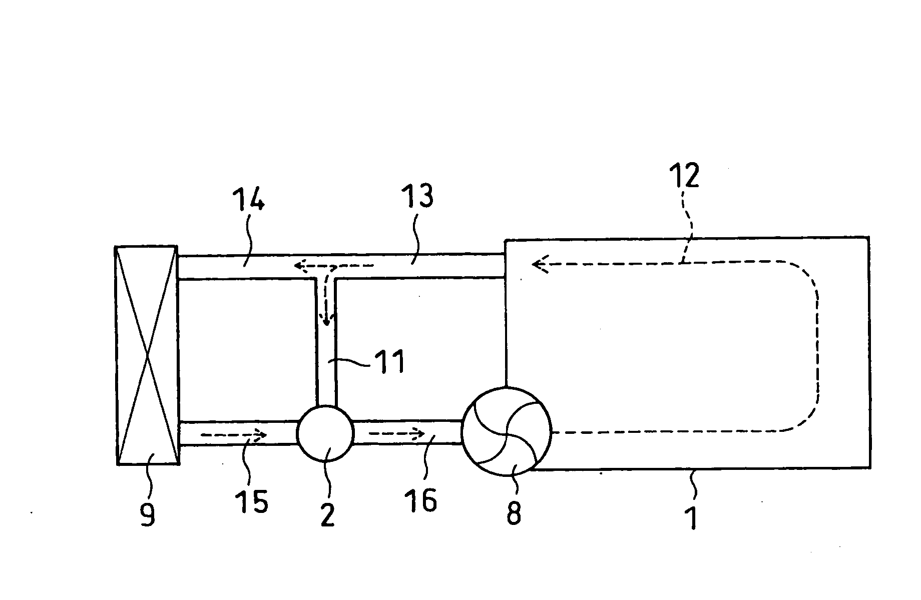
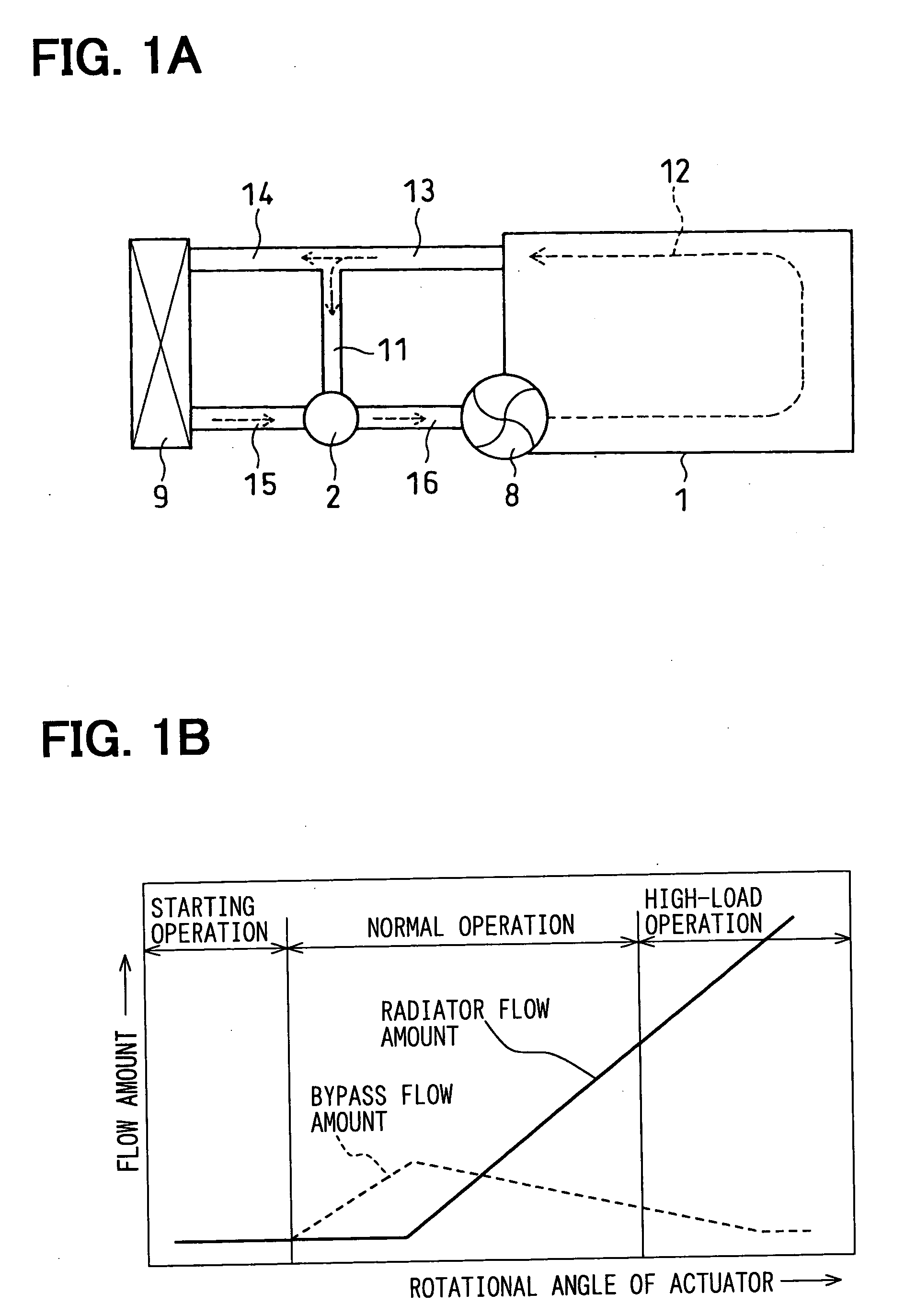
[0030]FIGS. 1A to 4C show a first embodiment of the present invention, wherein FIG. 1A shows a schematic view showing an engine cooling system for a water-cooled engine, and FIG. 1B is a graph showing characteristics of a radiator flow amount and a bypass flow amount with respect to a rotational angle of an actuator.

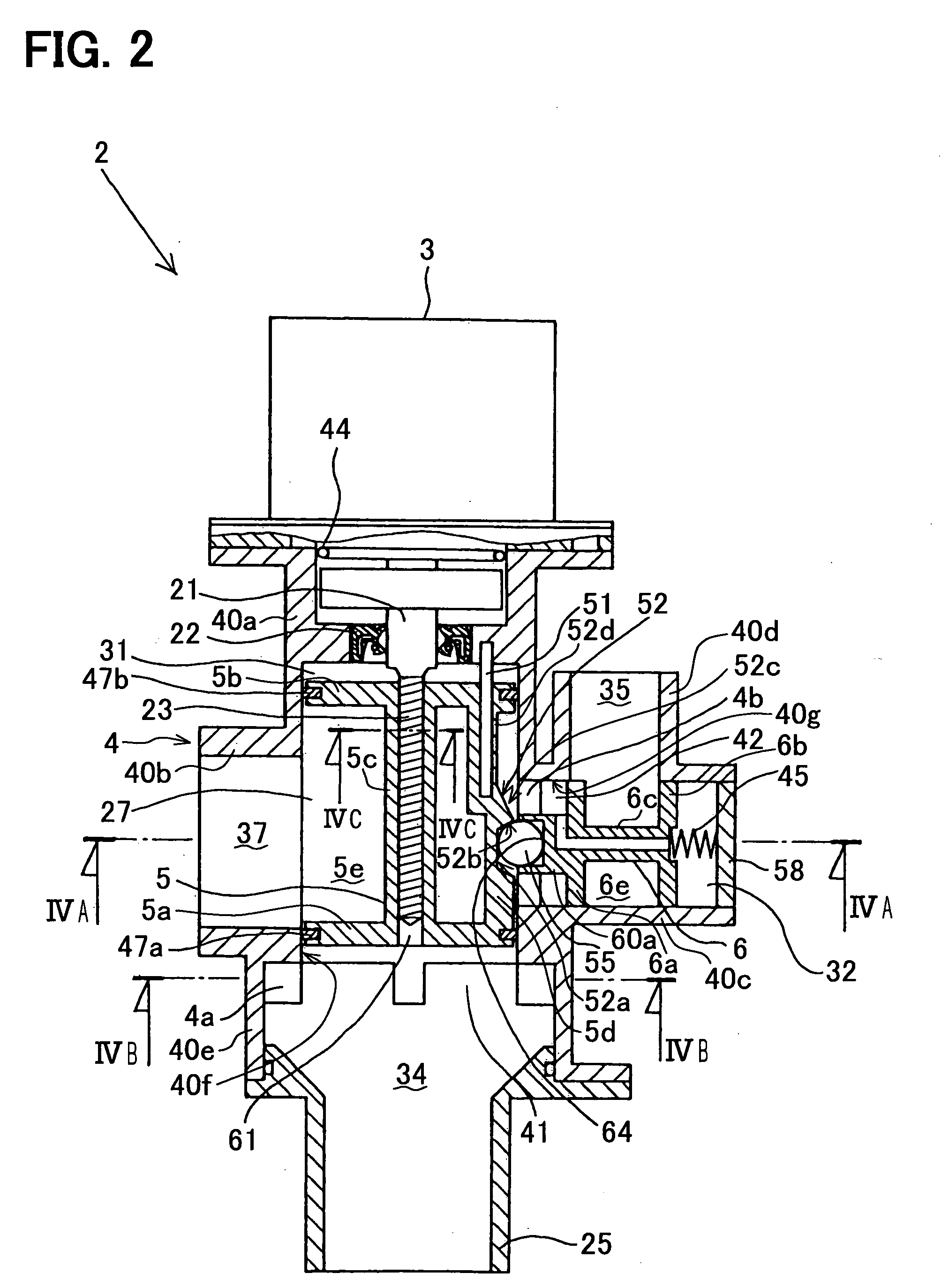
[0031] A flow control system according to the present invention comprises an engine cooling system for a water-cooled engine 1 having a cooling water circuit, a flow control valve 2 provided in the cooling water circuit, an electronic control unit (not shown and called hereinafter as ECU) for electronically controlling an opening degree of the flow control valve 2 depending on operational conditions of the engine 1. The flow control valve 2 comprises, as shown in FIG. 2, an actuator 3 to be electronically operated by the ECU, a valve housing 4 which also forms a part of an interfluent portion of the water cooling circuit, a valve body 5 (also referred to as a first spoo...

second embodiment

[0079] A second embodiment will be explained with reference to FIGS. 5A to 5D, wherein the second embodiment differs from the first embodiment in that the first pressure adjusting passage 61 is modified, instead of providing the cut-out portion 24 at the rotor shaft 21.

[0080]FIG. 5A shows a cross sectional view of the cylindrical portion 5c of the first spool valve 5. A part of the cylindrical portion 5c is extended in a radial direction to form the first pressure adjusting passage 61.

[0081]FIG. 5B also shows a cross sectional view of the cylindrical portion 5c of the first spool valve 5. Three parts of the cylindrical portion 5c are extended in radial directions to form multiple pressure adjusting passages 61.

[0082]FIG. 5C shows a vertical cross sectional view of the flow control valve 2, wherein the first pressure adjusting passage 61 is formed in the side wall portion 5d of the first spool valve 5.

[0083]FIG. 5D also shows a vertical cross sectional view of the flow control va...

third embodiment

[0086] A third embodiment will be explained with reference to FIG. 6.

[0087] The forward end 70 of the protruded small-diameter portion of the second spool valve 6 is formed into a semispherical shape, so that the ball 55 of the first embodiment can be eliminated. According to the third embodiment, the number of parts as well as number of assembling processes for the flow control valve can be reduced to realize a cost down.


PUM


Abstract

A flow control valve comprises a first valve for controlling a radiator flow amount and a second valve for controlling a bypass flow amount. Pressure adjusting passages are respectively provided for the first and second valves for communicating spaces formed at both sides of the respective valves to equalize fluid pressures at both sides, so that a pressure load in an axial direction to the respective valves can be eliminated. As a result, a driving force of an actuator of the flow control valve for directly or indirectly driving the first and second valves can be reduced.

Description


Claims


Application Information

Patent Timeline
Owner DENSO CORP
Why Eureka
Try Eureka